semi合集-English.pdf - 第128页
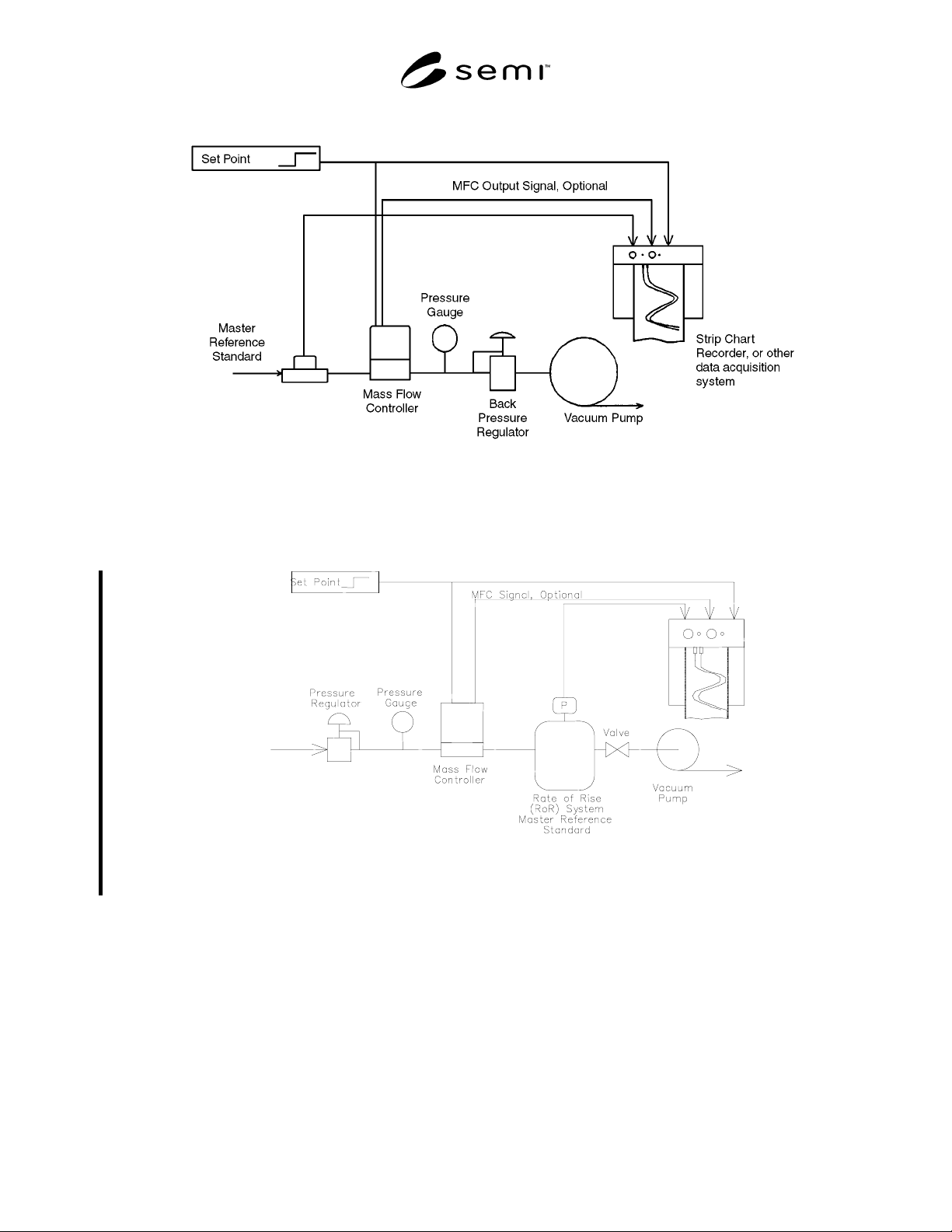
SEMI E17-0600 © SEMI 1991 , 2000 4 Figure 3b MFC Transient Characteristics Test Setup with Outlet at Vacuum Figure 3c VFC Transient Characteris t ics Test Setup w ith Rate of Rise (RoR) System 4 Test Pro cedure 4.1 Evalu…
SEMI E17-0600 © SEMI 1991, 20003
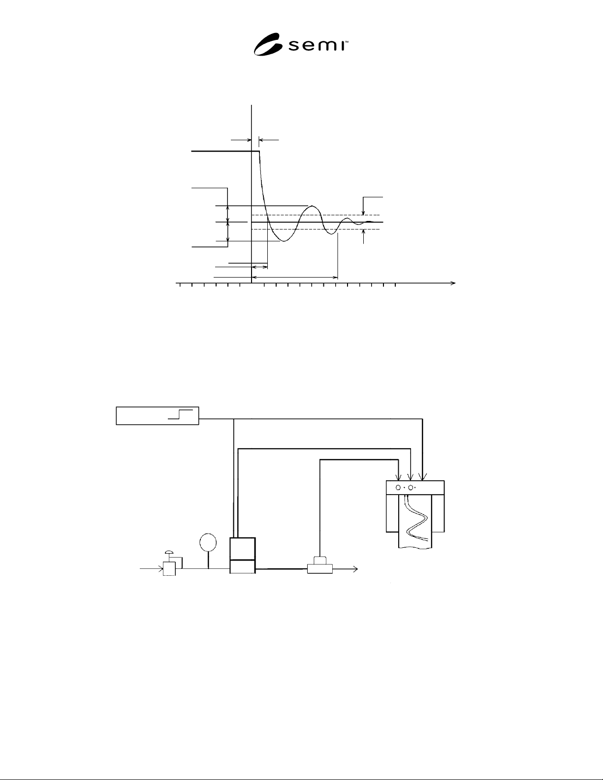
Dead Time (seconds)
Initial Set Point
Transient Undershoot
(% of Set Point Step Change)
Transient Overshoot
(% of Set Point Change)
Step Response Time (seconds)
Settling Time (seconds)
* ± 2% of the Final Steady State Value or
0.5% of Full Scale, whichever is greater
Final Steady State Flow
Specified Band
-5
t
0
5
10
Time (seconds)
Mass Flow Rate
(sccm or slsm)
Figure 2
Definitions of MFC Transient Characteristics Terminology in the Case
Where the Final Set Point Is Lower than the Initial Set Point
Set Point
Pressure
Gauge
Pressure
Regulator
Gas Supply
Mass Flow
Controller
Master Reference
Standard
Strip Chart
Recorder, or other
data acquisition
system
MFC Output Signal Optional
Figure 3a
MFC Transient Characteristics Test Setup with Outlet at Atmospheric Pressure
SEMI E17-0600 © SEMI 1991, 2000 4
Figure 3b
MFC Transient Characteristics Test Setup with Outlet at Vacuum
Figure 3c
VFC Transient Characteristics Test Setup with Rate of Rise (RoR) System
4 Test Procedure
4.1 Evaluate the transient characteristics from “OFF” to a flowing condition at final set point by a transition in set
point voltage only.
4.1.1 Apply a set point voltage sufficient to close the control valve following the manufacturer’s recommendation.
This may be a voltage other than zero, either positive or negative. Allow the output of the mass flow controller and
the actual flow, if any, to stabilize.
4.1.2 Apply the final set point value as shown in Table 1.

SEMI E17-0600 © SEMI 1991, 20005
4.2 Evaluate the transient characteristics from “OFF” to a flowing condition at final set point by using an auxiliary
input to an MFC designed for the purpose.
4.2.1 Establish an “OFF” condition following the manufacturer’s recommendation. The setpoint should be applied
as shown in Table 1. Allow the output of the mass flow controller and the actual flow, if any, to stabilize.
4.2.2 Change the state of the auxiliary input to achieve control.
4.3 Evaluate the testing transient characteristics between two non-zero set point controlled flows.
4.3.1 Adjust the command to the “initial set point” in Table 1, and allow the actual flow (as measured by the master
reference standard) to stabilize.
4.3.2 Apply final set point as shown in Table 1.
4.4 Refer to Figures 3 and 4 to determine the dead time, step response time, settling time, overshoot, and
undershoot. Record the results in Table 1.
5 Test Results
5.1 Transient characteristics test results shall be presented as follows:
(1) “OFF” means the MFC set point is zero or the lowest value permitted.
(2) The control valve leak rate at shut-off shall be recorded.
(3) Other initial and final set points may be tested and reported.
(4) The transient characteristics of the MFC electrical output signal shall also be recorded during the above testing
for purposes such as comparison with the actual flow.
Table 1
Initial Set Point
(% of Full Scale)
OFF
(1)
OFF
(1)
25 75
OTHER
(3)
Final Set Point
(% of Full Scale)
100 25 75 25 OTHER(3)
Dead Time
(Seconds)
Step Response Time
(Seconds)
Settling Time
(Seconds)
Transient Overshoot
(Percent of set point
step change)
Transient Undershoot
(Percent of set point
step change)
NOTICE: SEMI makes no warranties or representations as to the suitability of the guideline set forth herein for any
particular application. The determination of the suitability of the guideline is solely the responsibility of the user.
Users are cautioned to refer to manufacturer’s instructions, product labels, product data sheets, and other relevant
literature respecting any materials mentioned herein. These guidelines are subject to change without notice.
The user’s attention is called to the possibility that compliance with this guideline may require use of copyrighted
material or of an invention covered by patent rights. By publication of this guideline, SEMI takes no position
respecting the validity of any patent rights or copyrights asserted in connection with any item mentioned in this
guideline. Users of this guideline are expressly advised that determination of any such patent rights or copyrights,
and the risk of infringement of such rights, are entirely their own responsibility.
Copyright by SEMI® (Semiconductor Equipment and Materials
International), 3081 Zanker Road, San Jose, CA 95134. Reproduction o
f
the contents in whole or in part is forbidden without express written
consent of SEMI.