semi合集-English.pdf - 第131页
4.1.9.1 Description form: ___°C – __ _°C Figure 1 4.1.10 temperature effects — See Figure 2. NOTE 2: This section r equires that Gas Tem perature be the same as Ambient T emperature. 4.1.10.1 span effect — the change in …

SEMI E18-91 (Reapproved 1104)
GUIDELINE FOR TEMPERATURE SPECIFICATIONS OF THE MASS
FLOW CONTROLLER
This guideline was technically approved by the Global Gases Committee and is the direct responsibility of
the North American Gases Committee. Current edition approved by the North American Regional Standards
Committee on July 11, 2004. Initially available at www.semi.org September 2004; to be published
November 2004. Originally published, in 1991; last published February 1999.
1 Purpose
1.1 The purpose of this guideline is to establish a
uniform, worldwide means to describe the temperature
parameters which are characteristic of mass flow
controllers. It is intended to prevent confusion and
misunderstanding between manufacturers and users.
2 Scope
2.1 This guideline contains definitions of terms which
describe the effects of temperature upon mass flow
controllers as used in the semiconductor industry.
NOTICE: This standard does not purport to address
safety issues, if any, associated with its use. It is the
responsibility of the users of this standard to establish
appropriate safety and health practices and determine
the applicability of regulatory or other limitations prior
to use.
3 Referenced Standards
3.1 SEMI Standard
SEMI E12 — Standard for Standard Pressure,
Temperature, Density, and Flow Units Used in Mass
Flow Meters and Mass Flow Controllers
NOTICE: Unless otherwise indicated, all documents
cited shall be the latest published versions.
4 Terminology
4.1 Definitions (see Figure 1)
4.1.1 ambient temperature — the temperature of the
medium surrounding the device.
NOTE 1: The ambient temperature assumes that the
instrument is not exposed to significant radiant energy
sources.
4.1.2 calibration temperature — the ambient
temperature at which the mass flow controller was
calibrated.
4.1.2.1 Description Form: ___°C
CAUTION — Calibration Temperature is not to be
confused with Gas Temperature or Standard
Temperature.
4.1.3 gas temperature — the actual temperature of the
flowing gas at the primary flow standard.
4.1.4 maximum baking temperature — the highest
temperature to which the Mass Flow Controller or its
components in contact with the gas can be heated in
accordance with a specified baking procedure. The
specified baking process will not impair the
performance characteristics per the manufacturers
specifications. (“Baking” is a process whereby a device
is heated to accelerate the removal of adsorbed gases
and/or other volatile material).
4.1.4.1 Description Form: MAX. ___°C
4.1.5 normal operating temperature — the temperature
range within which the influence of ambient
temperature on the performance is stated.
4.1.5.1 Description Form: ___°C – ___°C
4.1.6 operating temperature limits — operation is
permitted within this range but performance is not
specified beyond the Normal Operating Temperature.
If the instrument is operated outside these limits
damage may occur.
4.1.6.1 Description Form: ___°C – ___°C
4.1.7 reference operating temperature — the range
within which accuracy statements apply without
requiring correction for Temperature Effects (see
Section 4.1.10).
4.1.7.1 Description Form: ___°C – ___°C
4.1.8 standard temperature — the temperature to
which a volumetric flow rate (measured at the Gas
Temperature) is referenced through the ideal gas law
(PV = nRT). SEMI E12 defines Standard Temperature
as 0.0°C.
CAUTION — Standard Temperature is not the same as
the Gas Temperature or Calibration Temperature.
4.1.9 storage temperature limits — the temperature
limits to which the mass flow controller may be
subjected in an unpowered condition. No permanent
impairment shall take place, however minor
adjustments may be needed to restore performance to
normal.
SEMI E18-91 © SEMI 1991, 2004 1
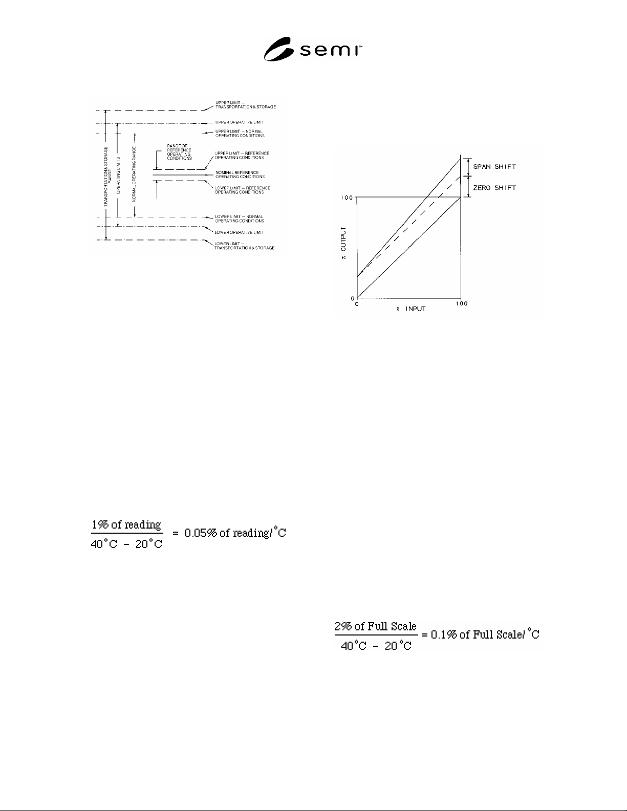
4.1.9.1 Description form: ___°C – ___°C
Figure 1
4.1.10 temperature effects — See Figure 2.
NOTE 2: This section requires that Gas Temperature be the
same as Ambient Temperature.
4.1.10.1 span effect — the change in span due to a
change in ambient temperature from one normal
operating temperature to a second normal operating
temperature. All other conditions must be held within
the limits of reference operating conditions.
4.1.10.1.1 The effect of temperature change on span
may be expressed as a coefficient calculated as the ratio
of percent of reading change in output to the
corresponding change in temperature. The change in
ambient temperature should be specified. This
coefficient is defined as the “temperature coefficient of
span.”
Example: Temperature coefficient of span may be
expressed as:
NOTE 3: If the relation between temperature and change in
output is linear, one coefficient will suffice.
4.1.10.1.2 If the temperature influence is non-linear a
different method of expression may be used. Two
examples:
1. The percent of span change in output will not
exceed a specified value for any value of
temperature within a specified temperature range.
Example: “± 1.0% of reading maximum error over
10°C to 50°C”
2. It may be desirable to state a series of coefficients
for successive increments of temperature within a
specified temperature range.
Figure 2
Span and Zero Shift
4.1.10.2 total effect — the change in output, including
zero and span, due to a change in Ambient Temperature
from one normal operating temperature to a second
normal operating temperature. All other conditions
must be held within the limits of reference operating
conditions.
4.1.10.3 zero effect — the change in zero due to a
change in ambient temperature from one normal
operating temperature to a second normal operating
temperature. All other conditions must be held within
the limits of reference operating conditions.
4.1.10.3.1 The effect of temperature change on zero
may be expressed as a coefficient calculated as the ratio
of full scale percent change in output to the
corresponding change in temperature. The change in
ambient temperature should be specified. This
coefficient is defined as the “temperature coefficient of
zero.”
Example: Temperature coefficient of zero may be
expressed as:
NOTE 4: If the relation between temperature and change in
output is linear, one coefficient will suffice.
4.1.10.3.2 If the temperature influence is non-linear a
different method of expression may be used. Two
examples:
SEMI E18-91 © SEMI 1991, 2004 2

1. The percent of full scale change in output will not
exceed a specified value for any value of
temperature within a specified temperature range.
Example: “± 1.5% of full scale maximum error over
10°C to 50°C”
2. It may be desirable to state a series of coefficients
for successive increments of temperature within a
specified temperature range.
4.1.11 units — degrees Celsius (C) is used as the
temperature unit.
NOTICE: SEMI makes no warranties or
representations as to the suitability of the standards set
forth herein for any particular application. The
determination of the suitability of the standard is solely
the responsibility of the user. Users are cautioned to
refer to manufacturer's instructions, product labels,
product data sheets, and other relevant literature,
respecting any materials or equipment mentioned
herein. These standards are subject to change without
notice.
By publication of this standard, Semiconductor
Equipment and Materials International (SEMI) takes no
position respecting the validity of any patent rights or
copyrights asserted in connection with any items
mentioned in this standard. Users of this standard are
expressly advised that determination of any such patent
rights or copyrights, and the risk of infringement of
such rights are entirely their own responsibility.
Copyright by SEMI® (Semiconductor Equipment and Materials
International), 3081 Zanker Road, San Jose, CA 95134. Reproduction of
the contents in whole or in part is forbidden without express written
consent of SEMI.
SEMI E18-91 © SEMI 1991, 2004 3