semi合集-English.pdf - 第6915页
SEMI S8-0705 © SEMI 1995, 2005 12 Section Indicator Acceptance Criteria Metric Units (US Customary Units) Actual Conforms/Does N ot Conform/Not Applicable 6.9.2 Finger pull hand les pull force (fo ur fingers) maximum 9.8…
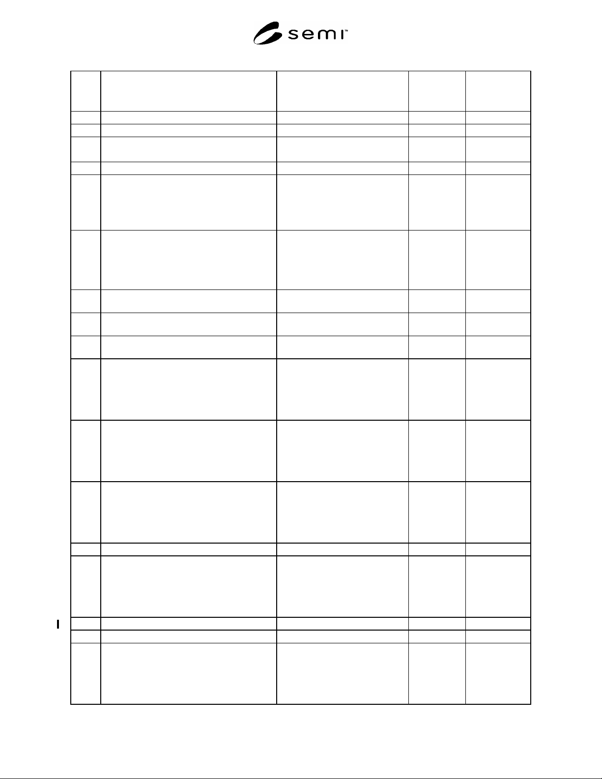
SEMI S8-0705 © SEMI 1995, 2005 11
Section Indicator
Acceptance Criteria
Metric Units (US Customary Units)
Actual
Conforms/Does
N
ot Conform/Not
Applicable
6.5.2 Pliers handle length (L) minimum 127 mm (5.0 in.)
6.6 Pistol grip handle
6.6.1 Pistol grip handle diameter (D) maximum 63 mm (2.5 in.)
minimum 38 mm (1.5 in.)
6.6.2 Pistol grip handle length (L) minimum 127 mm (5.0 in.)
6.7 Enclosed handles
NOTE: Handle diameter refers to the surface of
the handle presented to the inside of the curled
fingers. Enclosed handles need not be made
solely from cylindrical stock.
6.7.1 Enclosed handle, full hand power grip (suitcase
handle)
Width (W)
Depth (D)
Diameter (d)
minimum 127 mm (5.0 in.)
minimum 45 mm (1.75 in.)
maximum 25 mm (1.0 in.)
6.7.1.1 Diameter (d), requiring no greater than 71 N (16
lbf) force
minimum 6.3 mm (0.25 in.)
6.7.1.2 Diameter (d), requiring no greater than 89 N (20
lbf) force
minimum 13 mm (0.5 in.)
6.7.1.3 Diameter (d), requiring no greater than 180 N
(40 lbf) force
minimum 19 mm (0.75 in.)
6.7.2 Enclosed handle, three fingers
Width (W)
Depth (D)
Diameter (d)
Force
minimum 90 mm (3.5 in.)
minimum 38 mm (1.5 in.)
minimum 6.3 mm (0.25 in.)
maximum 71 N (16 lbf)
6.7.3 Enclosed handle, two fingers
Width (W)
Depth (D)
Diameter (d)
Force
minimum 60 mm (2.5 in.)
minimum 38 mm (1.5 in.)
minimum 6.3 mm (0.25 in.)
maximum 51 N (11.5 lbf)
6.7.4 Enclosed handle, one finger
Width (W)
Depth (D)
Diameter (d)
Force
minimum 38 mm (1.5 in.)
minimum 38 mm (1.5 in.)
minimum 3.2 mm (0.13 in.)
maximum 27 N (6 lbf)
6.8 Hook grasp handle
6.8.1 Hook grasp handle (four fingers)
Opening length (L)
Opening width (W)
Depth (d)
Lip length (l)
minimum 90 mm (3.5 in.)
minimum 38 mm (1.5 in.)
minimum 50 mm (2.0 in.)
minimum 50 mm (2.0 in.)
6.8.2 Hook grasp handle pull force (four fingers) maximum 80 N (18.0 lbf)
6.9 Finger pull handle
6.9.1 Finger pull handles (four fingers)
Opening length (L)
Opening width (W)
Depth (d)
Lip length (l)
minimum 90 mm (3.5 in.)
minimum 25 mm (1.0 in.)
minimum 19 mm (0.75 in.)
minimum 19 mm (0.75 in.)
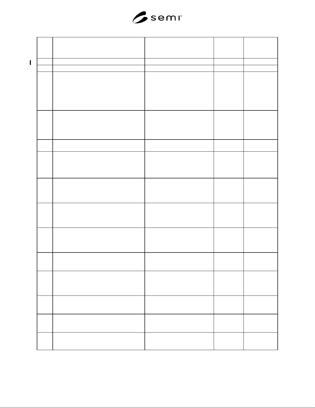
SEMI S8-0705 © SEMI 1995, 2005 12
Section Indicator
Acceptance Criteria
Metric Units (US Customary Units)
Actual
Conforms/Does
N
ot Conform/Not
Applicable
6.9.2 Finger pull handles pull force (four fingers) maximum 9.8 N (2.2 lbf)
7 Maintainability and Serviceability
7.1 Minimum lighting level in routine maintenance
areas is required where the operator has to read
information, use a hand tool, or make a
connection. This provision can be met by
providing integral lighting or portable lighting
which can be temporarily attached such that it
does not have to be hand held.
minimum 300 lux (30 fc)
7.2 Full Body Clearance
NOTE: Clearances should be approached from
a task analysis point of view. Clearances should
be provided based on the nature of the tasks
performed in the designated area.
7.2.1 Any posture: upper body clearance (shoulder
width)
minimum 610 mm (24 in.)
7.2.2 Standing:
overhead clearance, measured from the floor
forward horizontal clearance
#3
minimum 1980 mm (78 in.)
minimum 690 mm (27 in.)
7.2.3 Sitting-on-Floor:
overhead clearance, measured from the floor
forward horizontal clearance
#3
working height
minimum 1000 mm (39 in.)
minimum 690 mm (27 in.)
minimum 280 mm (11 in.)
7.2.4 Squatting:
overhead clearance, measured from the floor
forward horizontal clearance
#3
working height
minimum 1220 mm (48 in.)
minimum 790 mm (31 in.)
minimum 460 mm (18.1 in.)
7.2.5 Kneeling:
overhead clearance, measured from the floor
forward horizontal clearance
#3
working height
minimum 1450 mm (57 in.)
minimum 1220 mm (48 in.)
minimum 640 mm (25.2 in.)
7.2.6 Kneeling Crawl:
overhead clearance, measured from the floor
forward horizontal clearance
#3
minimum 740 mm (29 in.)
minimum 1520 mm (60 in.)
7.2.7 Stooping:
overhead clearance, measured from the floor
forward horizontal clearance
#3
working height
minimum 1450 mm (57 in.)
minimum 1020 mm (40 in.)
minimum 640 mm (25.2 in.)
7.2.8 Supine (lying on back):
height
length
minimum 430 mm (17 in.)
minimum 1980 mm (78 in.)
7.2.9 Prone or crawl space:
height
length
minimum 510 mm (20 in.)
minimum 2440 mm (96 in.)
7.3 Hand/Arm Clearance (where appropriate to do
so, dimensions have been adjusted for the use of
cleanroom gloves)
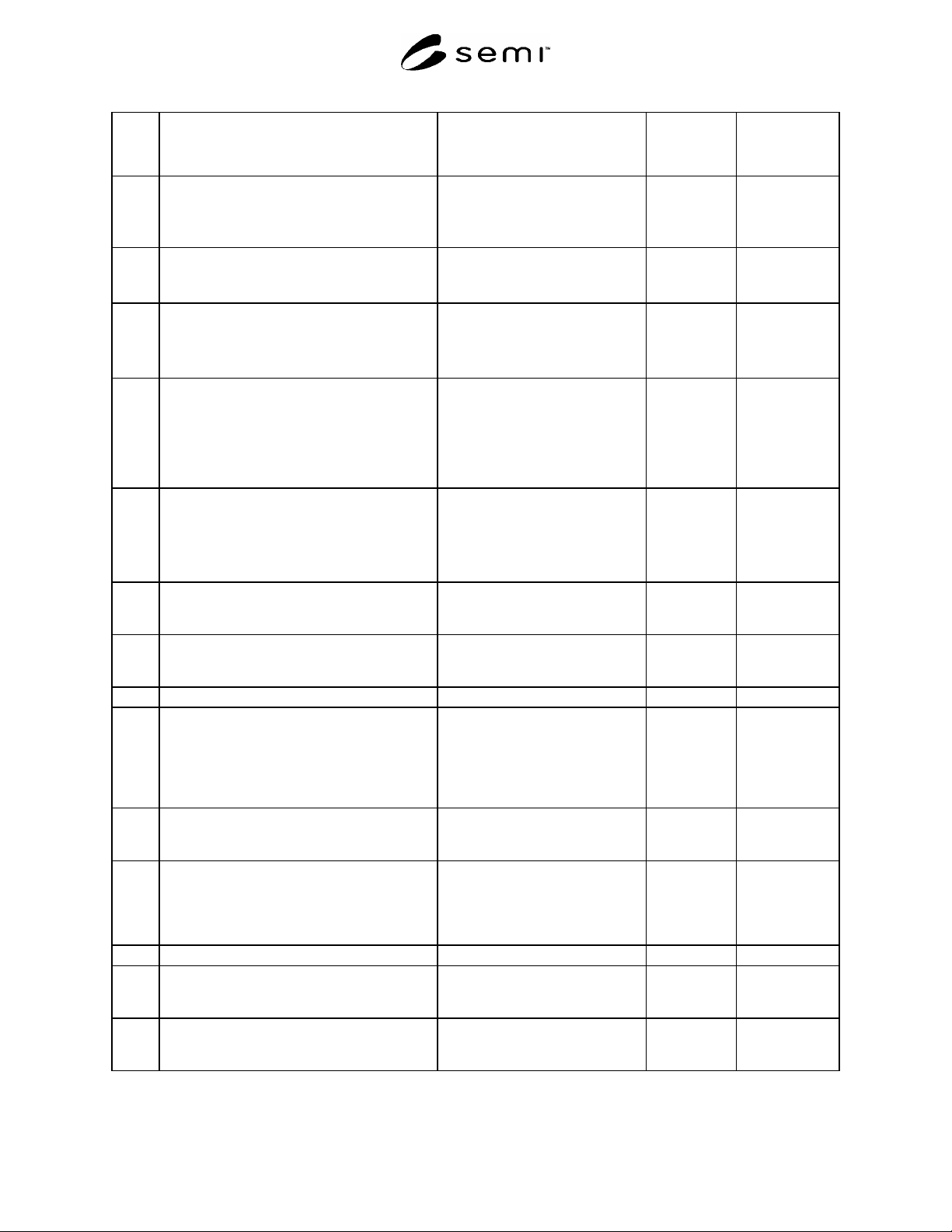
SEMI S8-0705 © SEMI 1995, 2005 13
Section Indicator
Acceptance Criteria
Metric Units (US Customary Units)
Actual
Conforms/Does
N
ot Conform/Not
Applicable
7.3.1 Clearance provided for finger access, round
(dia) or square:
one finger
2, 3, or 4 finger twist of small knob
minimum 32 mm (1.25 in.)
minimum object diameter + 58 mm
(2.3 in.)
7.3.2 Clearance provided for flat hand to wrist access:
height, palm thickness
width, palm width
minimum 89 mm (3.5 in.)
minimum 114 mm (4.5 in.)
7.3.3 Clearance provided for fist to wrist access:
height, palm thickness
width, palm width
minimum height 89 mm
(3.5 in.)
minimum width 127 mm (5.0 in.)
7.3.4 Clearance provided for two hands arm to
shoulders access (does not ensure visual
access):
reach
width
height
maximum 610 mm (24.0 in.)
minimum 483 mm (19 in.)
minimum 114 mm (4.5 in.)
7.3.5 Clearance provided for two hands, hand to wrist
access (does not ensure visual access):
reach
width
height
maximum 203 mm (8.0 in.)
minimum 191 mm (7.5 in.)
minimum 114 mm (4.5 in.)
7.3.6 Clearance provided for one arm to shoulder
access, diameter or square area (does not ensure
visual access).
minimum 132 mm (5.2 in.)
7.3.7 Clearance provided for one arm to elbow
access, diameter or square area (does not ensure
visual access).
minimum 119 mm (4.7 in.)
7.4 Maintenance and Service Access
7.4.1 Enclosures or covers must, unless fully
removable, be self-supporting, in the open
position, and not require manual support during
maintenance. Exceptions may be allowed for
self closing doors for fire safety or compliance
reasons.
Supports present
7.4.2 Access covers should be equipped with full-
handed grasp areas or other means for opening
them.
Handles present, refer to Section 6
for design criteria.
7.4.3 Height of access cover handle over the entire
range of motion required for operation or
maintenance. There should be no greater than a
254 mm (10 in.) deep obstruction in front of the
handle.
maximum 1700 mm (67 in.)
7.5 Replaceable Components
7.5.1 Serviceable components are replaceable as
modular packages, and are configured for rapid
removal and replacement.
Serviceable components configured
as described.
7.5.2 Serviceable components should not be stacked
directly on one another (i.e., a lower layer
should not support an upper layer).
Serviceable components
independently accessible.