semi合集-English.pdf - 第801页
SEMI E110-1102 © SEMI 2001, 2002 3 Table 1 Dimensions of indicator placement zone for a load port per SEMI E15.1 Option1 Symbol Used Figure Value Specifi ed Reference Measured From x400 1 237.5 mm (9.35 in.) bilateral da…
SEMI E110-1102 © SEMI 2001, 2002 2
4.1.4 horizontal datum plane — a horizontal plane from which projects the kinematic-coupling pins on which the
carrier sits. On tool load ports, it is at the load height specified in SEMI E15 and might not be physically realized as
a surface (as defined in SEMI E57).
4.1.5 indicator placement zone — a zone in which load port status indicators are placed.
4.1.6 internal buffer equipment — equipment that uses an internal buffer (as defined in SEMI E87).
4.1.7 load port operation interface — any indicator (e.g. lamp, LED) to visualize status information of a load port
to an operator and/or any switch to be used for manual handoff operation.
4.1.8 load port operation switch — any switch to be used for manual handoff operation.
4.1.9 load port status indicator — any indicator (e.g. lamp, LED) to visualize status information of a load port to an
operator.
4.1.10 switch placement volume — a volume in which load port operation switch is placed.
5 Requirements
5.1 Indicator placement zone
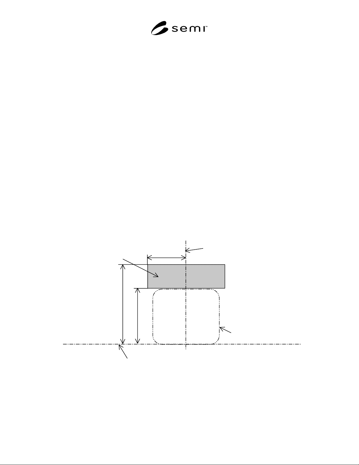
5.1.1 Indicator Placement Zone for a Load Port per SEMI E15.1 Option 1 — It is recommended that load port
status indicators should be positioned within a zone given by x400, z400, and z401. The exact placement of them
within this zone is at the direction of the load port supplier. They may be located at or behind (away from the
operator) the equipment boundary. Clearances required by SEMI E15.1 cannot be violated.
NOTE 2: The indicator placement zone is not an exclusion zone. No assumption can be made that this zone needs to be kept
empty by the load port supplier. Furthermore, no assumption can be made that a load port must have a physical surface
representing the indicator placement zone.
x400=237.5
z401=486
z400=340
Horizontal Datum Plane
C
L
Bilateral Datum Plane
Indicator placement zone
Approximate FOUP envelope
Figure 1
Indicator Placement Zone for a Load Port Per SEMI E15.1 Option 1
SEMI E110-1102 © SEMI 2001, 2002 3
Table 1 Dimensions of indicator placement zone for a load port per SEMI E15.1 Option1
Symbol Used Figure Value Specified Reference Measured From
x400 1 237.5 mm (9.35 in.) bilateral datum plane
z400 1
340 mm (13.39 in.)
horizontal datum plane
z401 1 486 mm (19.13 in.) horizontal datum plane
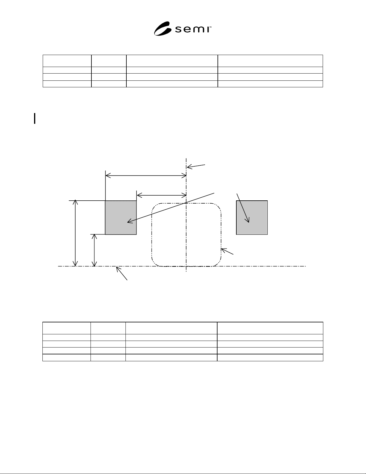
5.1.2 Indicator placement zone for a load port per SEMI E15.1 Option 3 — It is recommended that load port status
indicators should be positioned within a zone given by x401, x402, z402 and z403. The exact placement of them
within this zone is at the direction of the load port supplier. They may be located at or behind (away from the
operator) the load face plane. Clearances required by SEMI E15.1 cannot be violated.
NOTE 3: The indicator placement zone is not an exclusion zone. No assumption can be made that this zone needs to be kept
empty by the load port supplier. Furthermore, no assumption can be made that a load port must have a physical surface
representing the indicator placement zone.
x402=475
x401=290
z403=390
z402=190
Horizontal Datum Plane
C
L
Bilateral Datum Plane
Indicator placement zone
Approximate FOUP envelope
Figure 2
Indicator Placement Zone for a Load Port Per SEMI E15.1 Option 3
Table 2 Dimensions of indicator placement zone for a load port per SEMI E15.1 Option3
Symbol Used Figure Value Specified Reference Measured From
x401 2 290 mm (11.42 in.) bilateral datum plane
x402 2 475 mm (18.79 in.) bilateral datum plane
z402 2 190 mm (7.48 in.) horizontal datum plane
z403 2
390 mm (15.35 in.)
horizontal datum plane
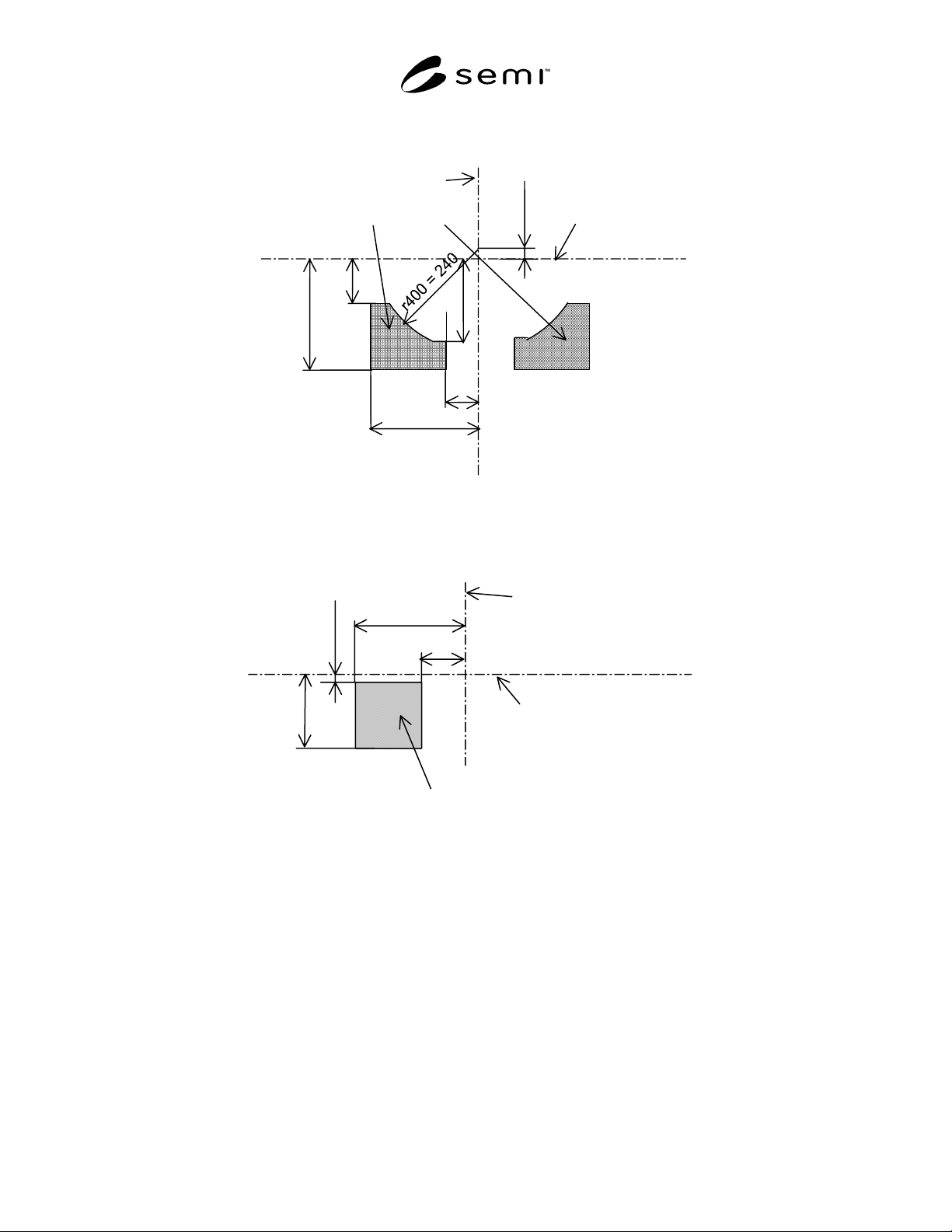
5.2 Switch Placement Volume — For a load port according to option 1 and 3 per SEMI E15.1, it is recommended
that load port operation switches should be positioned in a way, that the surface of the switch is within a volume
given by x403, x404, r400, y402 (equal to the maximum values of r67 and y53
defined in SEMI E47.1 respectively),
y400, y401 (equal to the maximum value of D defined in SEMI E15.1), z404, and z405. The exact placement of the
switches within this volume is at the discretion of the load port supplier.
NOTE 4: The switch placement volume is not an exclusion volume. No assumption can be made that this volume needs to be
kept empty by the load port supplier. Furthermore, no assumption can be made that a load port must have a physical surface
representing the switch placement volume.
SEMI E110-1102 © SEMI 2001, 2002 4
Y67=25
(Refer to
SEMI E47.1.)
Bilateral Datum Plane
C
L
Facial Datum Plane
Switch placement volume
x404=245
y400=100
x403=75
y401=250
y402=190
Figure 3
Top View of Switch Placement Volume
z405=165
Horizontal Datum Plane
C
L
Facial Datum Plane
Switch placement volume
y400=100
z404=15
y401=250
Figure 4
Side View of Switch Placement Volume