semi合集-English.pdf - 第852页
SEMI E114-0302 E © SEMI 2002 6 Estimate the Free-Space Length of Cable Assembly Physical Length Velocity of Propagation [] Is the Estimated Length Less Than a Quarter Wavelength at the Nominal Operating Frequency? Use Te…
SEMI E114-0302
E
© SEMI 2002 5
13.4 At the short circuit termination, the measurement
shall be made up to the point where the falling edge of
the impedance is equal to 90 percent of the nominal
impedance. For example, if the nominal impedance is
50 ohms, then the measurement can stop at the point
where the measured value at the short circuit
termination is equal to 45 ohms (0.9 × 50 = 45). An
example plot showing the measurement termination
point is shown in Figure 5.
NOTE 1: The termination point can be verified by
disconnecting the short circuit termination and observing that
the impedance increases rapidly due to the open circuit.
14 Reporting Test Results
14.1 Report the type of Network Analyzer and the
details of the Network Analyzer parameters used for the
tests, including the bandwidth, the number of data
points, the test frequency, and the frequency span (if
any). An example data sheet is shown in Table 1.
14.2 Report the type of Time Domain Reflectometer
used for the test.
14.3 Report the length of the cable assembly in terms
of degrees at the nominal operating frequency.
14.4 Report the power dissipation in terms of dB
(decibels) and percentage of power transfer.
14.5 Report the variation in characteristic impedance in
terms of the minimum and maximum after the values
have been scaled according to the reference 50-ohm
load.
15 Related Documents
15.1 IEEE Standards
1
IEEE-STD-572 — IEEE Standard for Qualification of
Class 1E Connection Assemblies for Nuclear Power
Generating Stations
15.2 MIL-Specifications
2
MIL-PRF-31031A — General Specification for
Connectors, Electrical, Plugs and Receptacles, Coaxial,
Radio Frequency, High Reliability, for Flexible and
Semirigid Cables
MIL-STD-348A — Radio Frequency Connector
Interfaces for MIL-C-3643, MIL-C-3650, MIL-C-3655,
MIL-C-25516, MIL-C-26637, MIL-PRF-39012, MIL-
PRF-49142, MIL-PRF-55339, and MIL C-83517
MIL-STD-220B — Test Method Standard: Method of
Insertion Loss Measurement
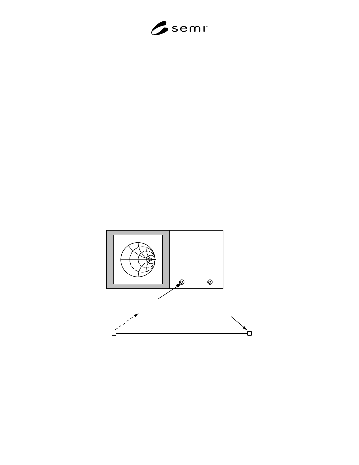
Port 1
Short Circuit
Termination
Cable Assembly to be tested
Network
A
nal
y
zer
NOTE: The reflection coefficient calibration is at the Port 1 output. The cable assembly to be tested (DUT) attaches to Port 1
and is terminated with a short circuit.
Figure 1
Schematic of the Network Analyzer Test Setup for the Electrical Length Measurement
SEMI E114-0302
E
© SEMI 2002 6
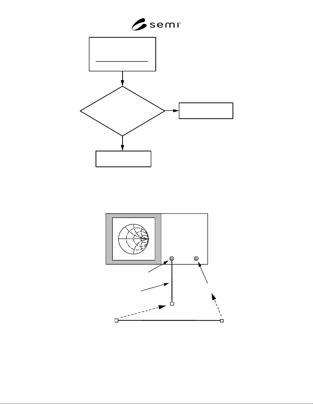
Estimate the
Free-Space Length
of Cable Assembly
Physical Length
Velocity of Propagation
[]
Is the
Estimated Length
Less Than a Quarter Wavelength
at the Nominal Operating
Frequency?
Use Test Method 1
to Measure Wavelength
Use Test Method 2
to Measure Wavelength
Yes
No
Figure 2
Flow Chart Showing the Steps to Chose the Appropriate Test Method for Determining Electrical Length of
the Cable Assembly
Port 1
Port 2
A
dditional Test Cable
Cable Assembly to be tested
Network
A
nal
y
zer
NOTE: Both the Port 1 and Port 2 outputs need to be used for the measurement. An additional test cable is needed for the
transmission calibration between the two ports. The cable assembly to be tested (DUT) attaches between the additional test cable
on Port 1 and Port 2.
Figure 3
Schematic of the Network Analyzer Test Setup for the Power Dissipation (loss) Measurement
SEMI E114-0302
E
© SEMI 2002 7
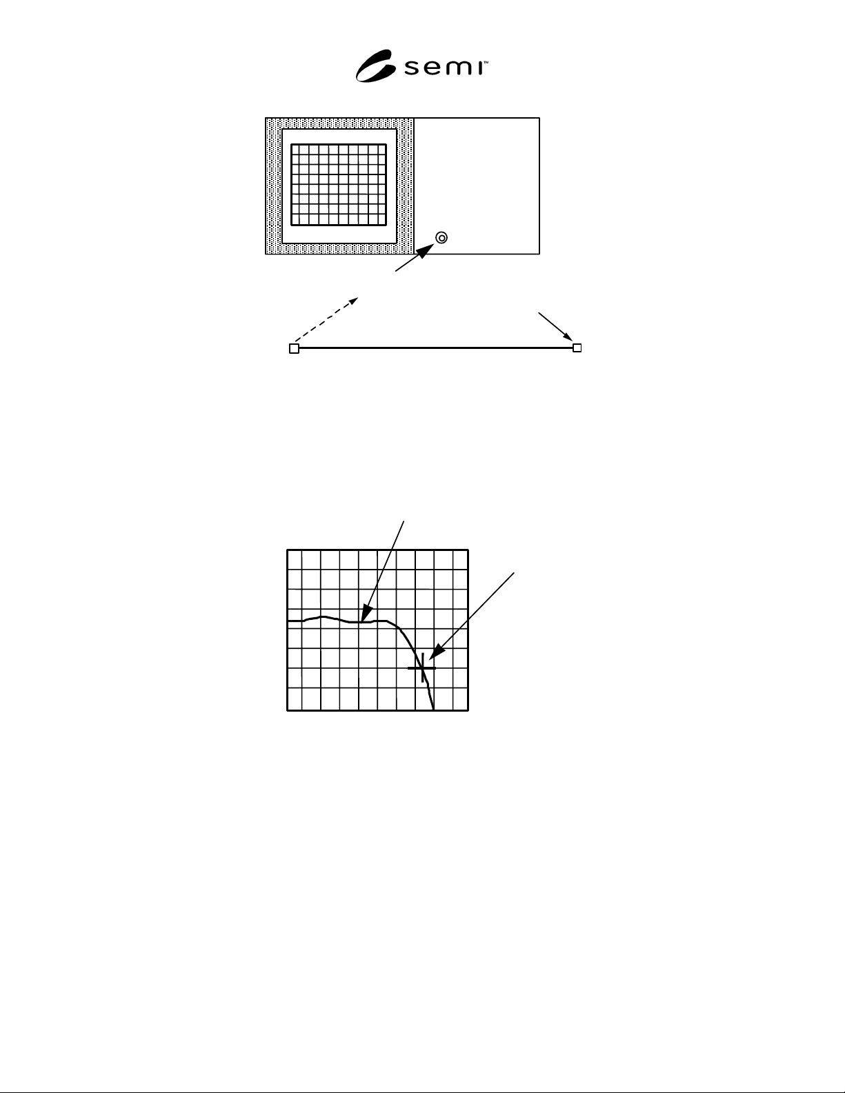
Short Circuit
Termination
Cable Assembly to be tested
Test Port
TDR
NOTE: The cable assembly to be tested (DUT) attaches to the test port and is terminated with a short circuit.
Figure 4
Schematic of the Time Domain Reflectometer (TDR) Test Setup for the Characteristic Impedance
Measurement
Point where impedance
is 45 ohms
50
45
40
55
60
Test Data Curve near
short circuit termination
Distance
Impedance
NOTE: The measurement termination point is defined as where the impedance at the short is equal to 0.9 times the nominal
impedance value, which would be 45 ohms for a 50-ohm nominal impedance.
Figure 5
Example Plot of the Characteristic Impedance of a 50-ohm Cable Assembly Near the Short Circuit
Termination