semi合集-English.pdf - 第1627页
SEMI E38-1296 © SEMI 1995 , 1996 16 Figure 15 Transp ort M odule Prim ary Control Message Flow Figure 16 Module Exce ption M essage Flow Figure 17 Module Recipe M essage Flow Figure 18 Module Event Reporting M essage Flo…
SEMI E38-1296 © SEMI 1995, 199615
as required. Collection events may initiate and
terminate the tracing in order to link reporting to
significant conditions, such as processing. The trace
data is collected at a frequency specified by the service-
user. Trace reports are generated according to the trace
report definition and the associated data report
definition.
Through associating the event report and trace report
definition with the service-user, the model provides for
the association of multiple service-users to a single
service-provider. This allows for event reporting
between modules where needed as well as the ability
for direct connection of a data acquisition entity
independent of the cluster controller.
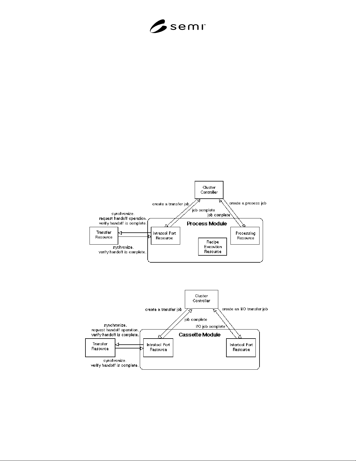
7.2 Cluster Tool Module Message Flow — The
appropriate objects in the information models in the
previous section are grouped in the cluster tool module
types. The communications with the essential objects
are shown in the message flow diagrams in this section.
The diagrams show message flow between entities
within an agent (in this case a module) and those
outside the agent. Entities are rectangular boxes, and
the agent is a rounded box. As emphasis is on the
module and its services, only one agent is shown on
each diagram. Outside entities in the cluster tool
module communications domain appear within an agent
on another diagram. The messaging is shown by arrows
in each direction, with a brief label indicating the
services requested or provided.
The communications are shown for the primary control
of the process module (Figure 13), cassette module
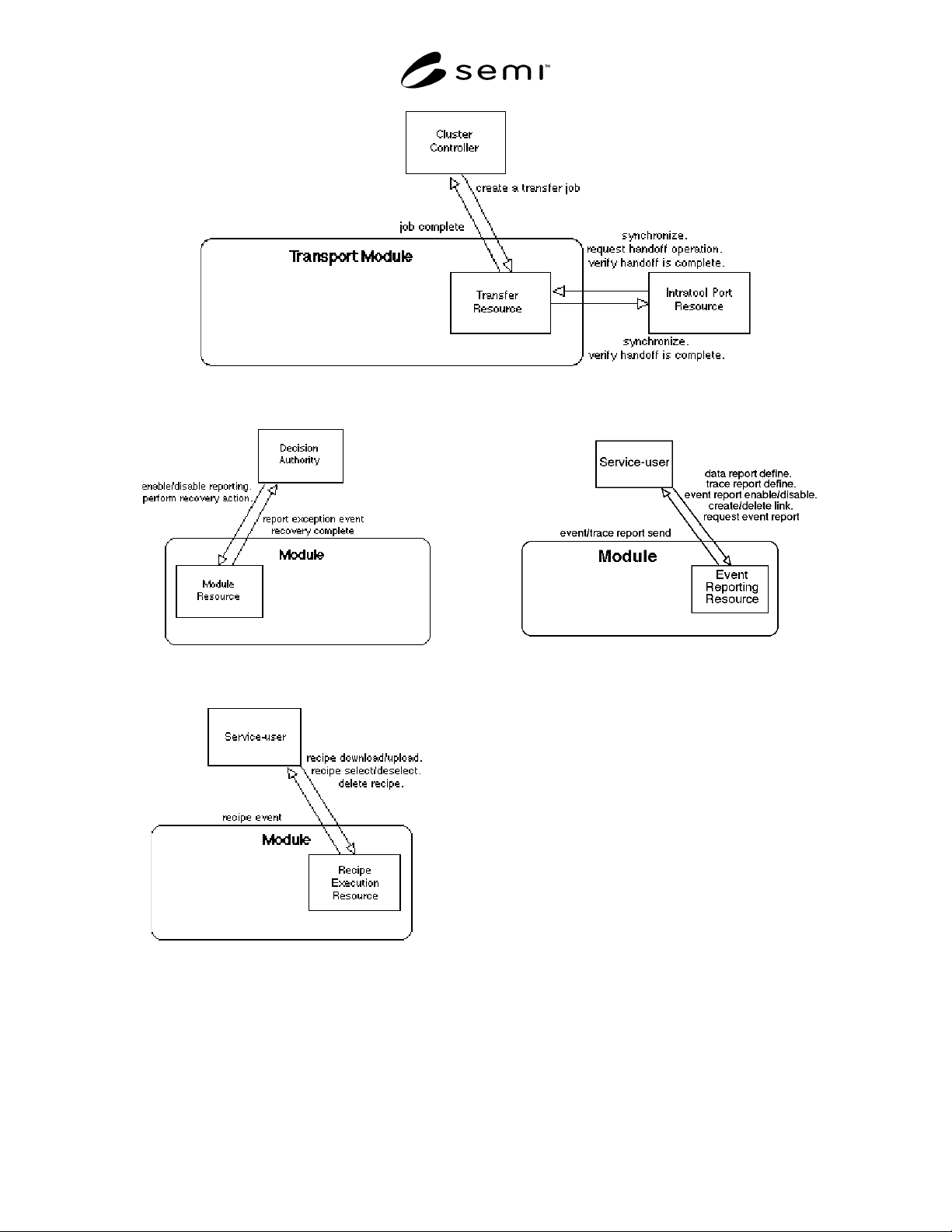
(Figure 14), and transport module (Figure 15). Note that
the transport module transfer resource communicates
with multiple process and cassette module intratool port
resources.
Figure 13
Process Module Primary Control Message Flow
Figure 14
Cassette Module Primary Control Message Flow
SEMI E38-1296 © SEMI 1995, 1996 16
Figure 15
Transport Module Primary Control Message Flow
Figure 16
Module Exception Message Flow
Figure 17
Module Recipe Message Flow
Figure 18
Module Event Reporting Message Flow
The communications for support functionality are
shown for any module, as the services are common to
all module types. The support functionality modeled
includes exception handling (Figure 16), recipe
management (Figure 17), and event reporting (Figure
18). A typical decision authority or service-user is the
cluster controller.
7.3 Cluster Tool Behavioral Model — The process
material is the fundamentally important object in a
cluster tool and its lifecycle is the key component to
establishing cohesiveness in the communication and
controls standards.
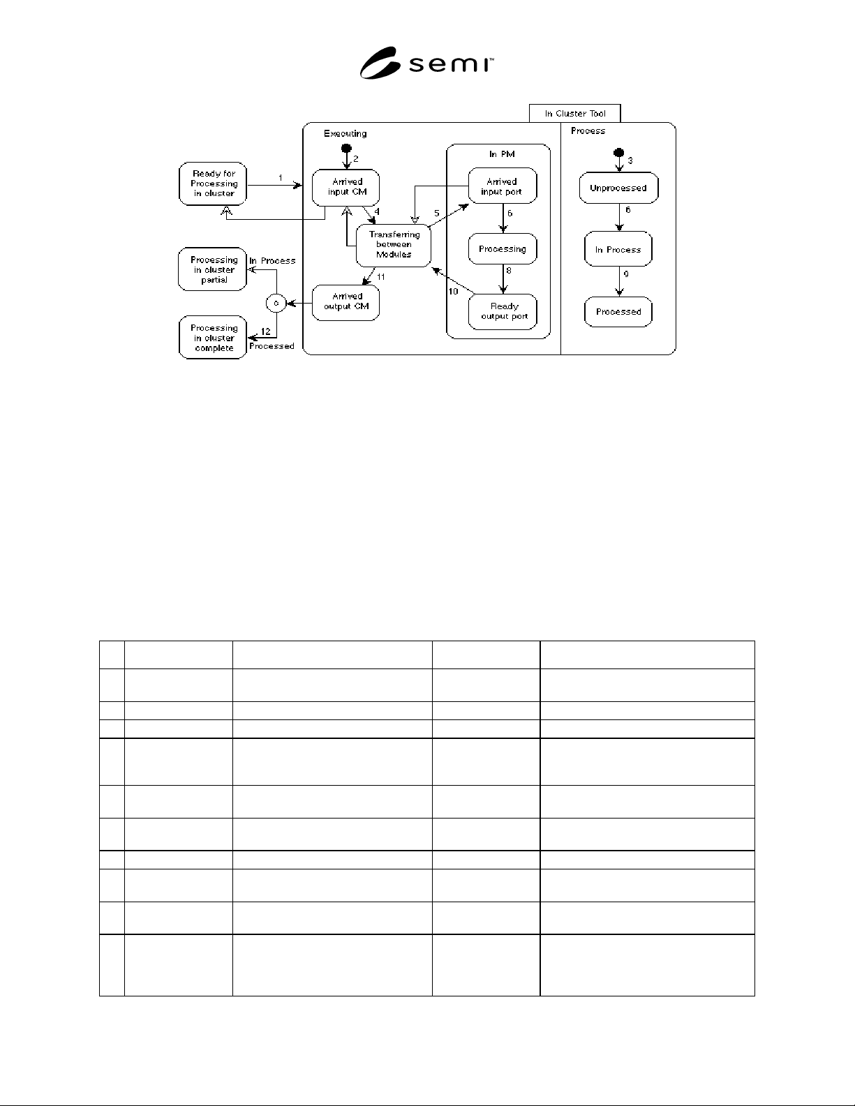
The finite state model in Figure 19 presents the high-
level behavior of a single material within the domain of
the cluster tool. Bold transitions trace the normal
lifecycle of the material and are described in the
transition table, Table 1. Other transitions occur in
exception situations and are not detailed here. The
transition table actions indicate the primary control
operations which are requested of the modules by the
cluster controller.
SEMI E38-1296 © SEMI 1995, 199617
Figure 19
Cluster Tool Material State Model
When ready to be processed in the cluster tool, the material is presented and loaded at the input cassette module
(intertool material transfer). It is usually contained with other single material in a cassette. The material process sub-
state in the scope of this visit to the cluster tool is initially unprocessed. The material is then transferred to the first
process module (intratool material transfer), ready for process. At this point, the material may be returned to the
input cassette module and back to the factory, as the material has not been physically altered.
The material then begins processing in the process module according to the recipe for that process step (process job),
and the process sub-state changes to in-process.
On successful completion of the process step, the material is then ready to be transferred to the next module
(intratool material transfer). This may be another process module for the next process step or to the output cassette
module if processing in the cluster tool is complete, in which case the process sub-state changes to processed. It is
also possible that the next process step be performed in the same process module.
Table 1 Cluster Material State Transition Table
# Current State Trigger New State Action(s)
1 Ready for
Processing in cluster
Material being received at cluster CM. In cluster tool CM Input/Output Transfer Job. CM
Carrier mapping.
2 Not in Cluster tool Material being received at cluster CM. Arrived input CM
3 Not in Cluster tool Material being received at cluster CM. Unprocessed
4 Arrived input CM Initiate material transfer to PM. Transferring
between modules
Initiate PM Process Job. TM Transfer
Job. Source AM Transfer Job (CM send).
Dest. AM Transfer Job (PM receive).
5 Transferring
between Modules
Material arrived in PM. In PM/Arrived input
port
6 In PM/Arrived input
port
Processing initiated on material. In PM/Processing PM Process the material.
7 Unprocessed Processing initiated on material. In Process
8 In PM/Processing PM processing complete. In PM/Ready output
port
9 In Process All required process steps in cluster
completed.
Processed
10 In PM/Ready output
port
Initiate intratool material transfer. Transferring
between modules
Initiate next PM Process Job if material
processing still required. TM Transfer
Job. Source AM Transfer Job (send).
Dest. AM Transfer Job (receive).