semi合集-English.pdf - 第283页
SEMI E47-0301 © SEMI 1995 , 2001 2 6.6 A n option al handle to be place d at t he top of the pod is specifi ed i n SEMI E47.1 (Sect ion 6.9 , Figu re 12, and Table 1). If used for 150 mm or 200 mm pods, thi s “top robot …

SEMI E47-0301 © SEMI 1995, 20011
SEMI E47-0301
SPECIFICATION FOR 150 mm/200 mm POD HANDLES
This specification was technically approved by the Global Physical Interfaces & Carriers Committee and is
the direct responsibility of the European Equipment Automation Committee. Current edition approved by the
European Regional Standards Committee on October 26, 2000. Initially available at www.semi.org January
2001; to be published March 2001. Originally published in 1995; previously published October 2000.
1 Purpose
1.1 This specification provides a unified form and
location for pod handles to enable automatic pod
handling.
2 Scope
2.1 This specification defines the dimensions and
location of handles on 150 mm/200 mm pod. These
provide automatic handling and take into consideration
manual handling. The design of individual manual
handles is open to be accomplished within the
dimensional limitations of the standard.
2.2 This standard does not purport to address safety
issues, if any, associated with its use. It is the
responsibility of the users of this standard to establish
appropriate safety and health practices and determine
the applicability of regulatory limitations prior to use.
3 Limitations
3.1 This specification applies only to automatic
handling of the pod with a SMIF interface in the
horizontal plane (see limitations of SEMI E19.3 and
E19.4). Dimensional restrictions for manual handling
are given in SEMI E15 and SEMI T4.
4 Referenced Standards
4.1 SEMI Standards
SEMI E15 — Specification for Tool Load Port
SEMI E19.3 — 150 mm Standard Mechanical Interface
(SMIF)
SEMI E19.4 — 200 mm Standard Mechanical Interface
(SMIF)
SEMI E47.1 — Provisional Mechanical Specification
for Boxes and Pods Used to Transport and Store 300
mm Wafers
SEMI T4 — Specification for 150 mm and 200 mm
Pod Identification Dimensions
NOTE 1: As listed or revised, all documents cited shall be the
latest publications of adopted standards.
5 Terminology
5.1 standard mechanical interface (SMIF) — the
interface plane between a pod and another
minienvironment per SEMI E19.
5.2 pod — a box having a Standard Mechanical
Interface (SMIF) per SEMI E19.
5.3 box — a protective portable container for a
cassette and/or substrate(s).
5.4 cassette — an open structure that holds one or
more substrates (wafer, masks, etc.).
5.5 handle of a pod — a mechanical aid designed for
automatic handling of a pod, which may also be used
for manual handling.
5.6 handling area — minimum free space around the
pod for automatic handling.
5.7 handling of a pod — automatic and manual
movement and/or placement of a pod.
5.8 orientation notch — notch located at the pod
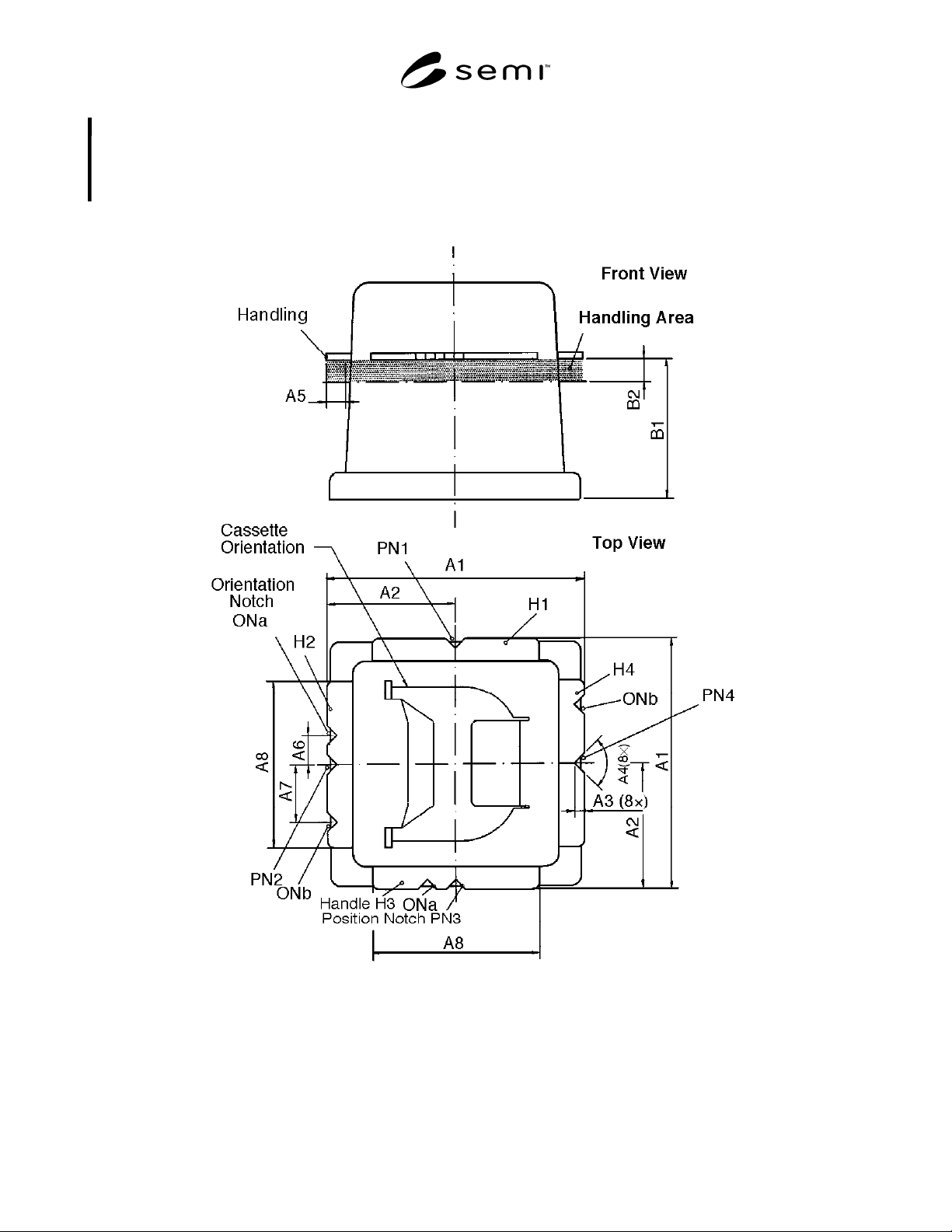
handles to allow sensing the orientation of the pod. See
Figure 1.
5.9 position notch — notch located at the center lines
of the pod handles to allow positioning. See Figure 1
(PN1 to PN4).
6 Requirements
6.1 Handling Dimensions: the han dling dimensions for
150 mm and 200 mm pods shall be per Table 1 (see
Figure 1 for dimensional locations).
6.2 A8 is given as a minimum and can be extended up
to A1.
6.3 Number of handles shall be:
6.3.1 four (H1–H4 in Figure 2) or
6.3.2 two (H1 and H3) in Figure 2.
6.4 The handling area is defined by A5 (which is in
reference to A1) and by B2. B1 is the minimum
distance between the interface plane and the nearest
extension of the handle.
6.5 The orientation possibilities of the pod are given in
Figure 2 and Table 2.
SEMI E47-0301 © SEMI 1995, 2001 2
6.6 An optional handle to be placed at the top of the pod is specified in SEMI E47.1 (Section 6.9, Figure 12, and
Table 1). If used for 150 mm or 200 mm pods, this “top robotic handling flange” has to meet the required
dimensions as specified in SEMI E47.1 (see Figure 12 of SEMI E47.1). Its center is to be placed above the center of
the cassette in the pod with the two orientation notches at the side where the cassette is accessed to remove wafers.
The orientation possibilities of the pod are then the same as described in Section 6.5 above and Table 2.
Figure 1
Pod Handling Terminology and Dimensions
SEMI E47-0301 © SEMI 1995, 20013
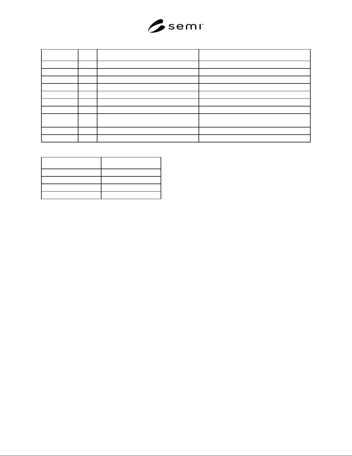
Table 1
Handling Dimensions for 150 mm (6 in.) Pod Handling Dimensions for 200 mm (8 in.) Pod
Handle: A1 215.0 mm ± 0.5 mm (8.464" ± 0.019") 305.0 mm ± 0.5 mm (12.008" ± 0.019")
A2 107.50 mm ± 0.25 mm (4.232" ± 0.01") 152.50 mm ± 0.25 mm (6.004" ± 0.01")
A3 6.0 mm ± 0.2 mm (0.236" ± 0.008") 5.65 mm ± 0.2 mm (0.222" ± 0.008")
A4 90° ± 0.2° 90° ± 0.2° (90° ± 0.2°)
A5 14 mm min. (0.551" min.) 20 mm min. (0.787" min.)
A6 30 mm ± 0.2 mm (1.181" ± 0.008") 30.0 mm ± 0.2 mm (1.181" ± 0.008")
A7 50 mm ± 0.2 mm (1.969" ± 0.008") 50.0 mm ± 0.2 mm (1.969" ± 0.008")
A8 148 mm min., 215 mm max. (A1)
(5.827" min., 8.464" max.)
148 mm min., 305 mm max. (A1)
(5.827" min., 12.008" max.)
Handle Height: B1 158 mm ± 1.0 mm (6.220" ± 0.039") 150.4 mm ± 1.0 mm (5.921" ± 0.039")
Handling Area: B2 30 mm min. (1.181" min.) 30 mm min. (1.181" min.)
Table 2
Orientation # Orientation Notch
1void
2 ON a
3 ON b
4 ON a+b