semi合集-English.pdf - 第4472页
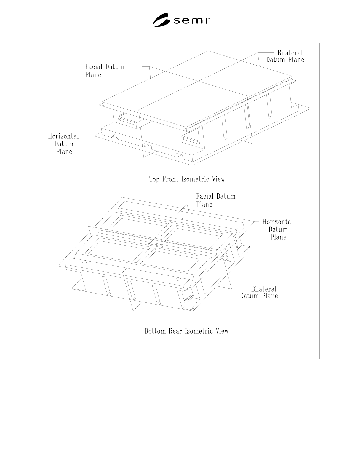
SEMI D17-0200 © SEMI 1998, 2000 7 Figure 1 Isometric Vie ws
SEMI D17-0200 © SEMI 1998, 2000 6
Symbol
Used
Shown In Datum Measured From Boundary or Feature Measured To Algebraic
Relation or Value
y9 Figure 2 facial datum plane outside edge of cassette top and bottom
plate domain
≤ L * 1.21
y10 Figure 3 facial datum plane inside edge of cassette top and bottom
plate indent
≤ L * 0.985
y11 Figure 3 facial datum plane inside edge of cassette sensing pad areas ≥ L * 0.708
y12 Figure 3 facial datum plane outside edge of cassette sensing pad
areas
≤ L * 0.954
y13 Figure 3 facial datum plane center of coupling exclusion zones
= L * 0.923 ±
0.1 mm
z1 Figure 4 horizontal datum plane bottom of cassette bottom domain
≥ 2 mm
z2 Figure 4 horizontal datum plane bottom of cassette sensing pads
= 3 ± 0.5 mm
z3 Figure 6 horizontal datum plane bottom surface of conveying surface
= 2 ± 0.5 mm
z4 Figure 4 horizontal datum plane top of cassette bottom domain
≤ 40 mm
z5 Figure 4 horizontal datum plane bottom nominal substrate seating plane = 60 mm
z6 Figure 4 each nominal substrate seating plane bottom of substrate
= ± 0.5 mm
z7 Figure 4 each nominal substrate seating plane encroachment of cassette side domains
on clearance above the substrate
See Table 4.
z8 Figure 4 each nominal substrate seating plane adjacent nominal substrate seating planes See Table 4.
z9 Figure 4 top nominal substrate seating plane bottom of cassette top domain
≥ z7 + 1 mm
z10 Figure 4 top nominal substrate seating plane bottom of clearance under robotic
handling flange
≤ 30 mm
z11 Figure 4 top nominal substrate seating plane top of clearance under robotic handling
flange
= 40 ± 1 mm
z12 Figure 4 top nominal substrate seating plane top of top cassette domain
≤ 50 mm
z14 Figure 6 horizontal datum plane top of v-rail, v-groove, and float roller
exclusion zones
= 24.86 ±
0.12 mm
SEMI D17-0200 © SEMI 1998, 20007
Figure 1
Isometric Views
SEMI D17-0200 © SEMI 1998, 2000 8
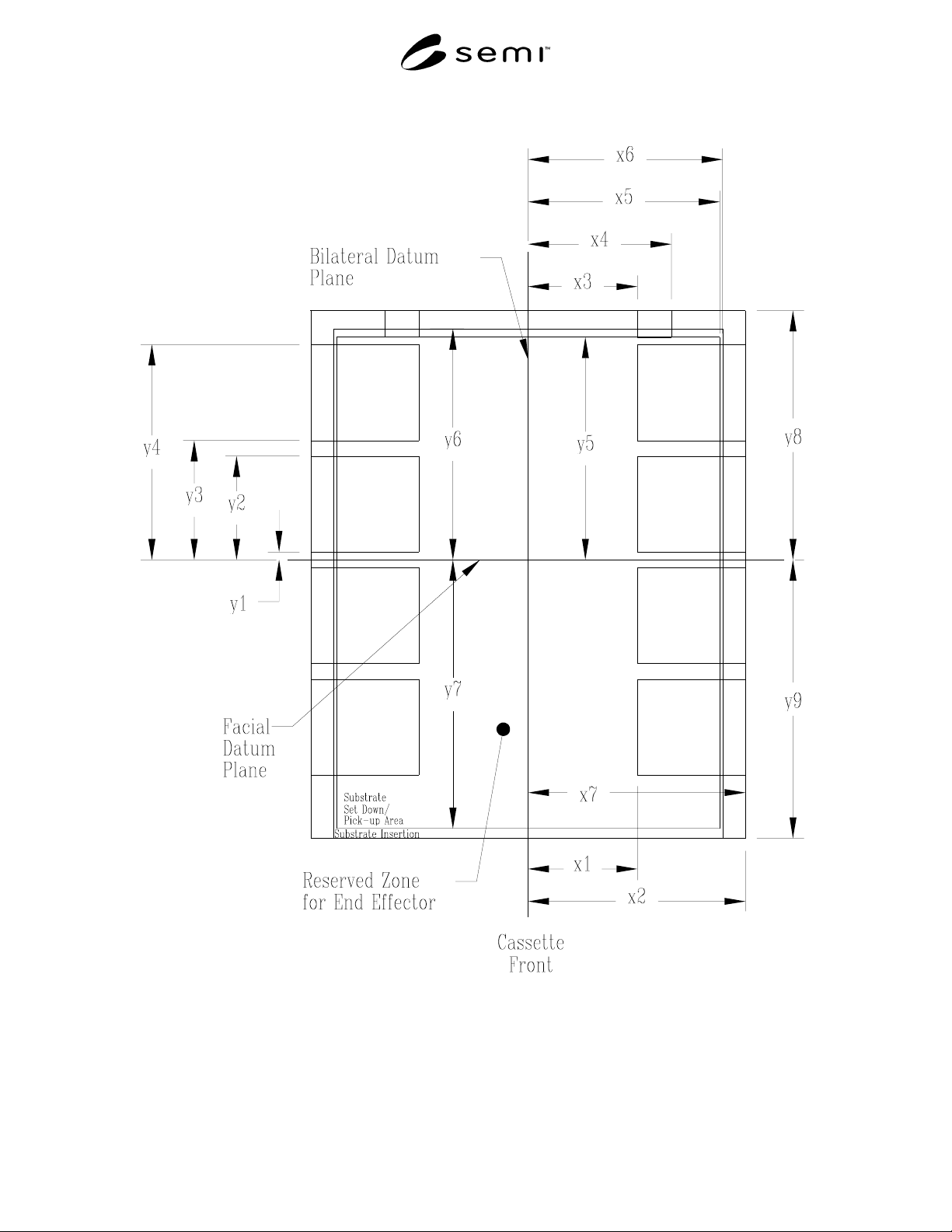
Figure 2
Cassette Side Domains