semi合集-English.pdf - 第518页
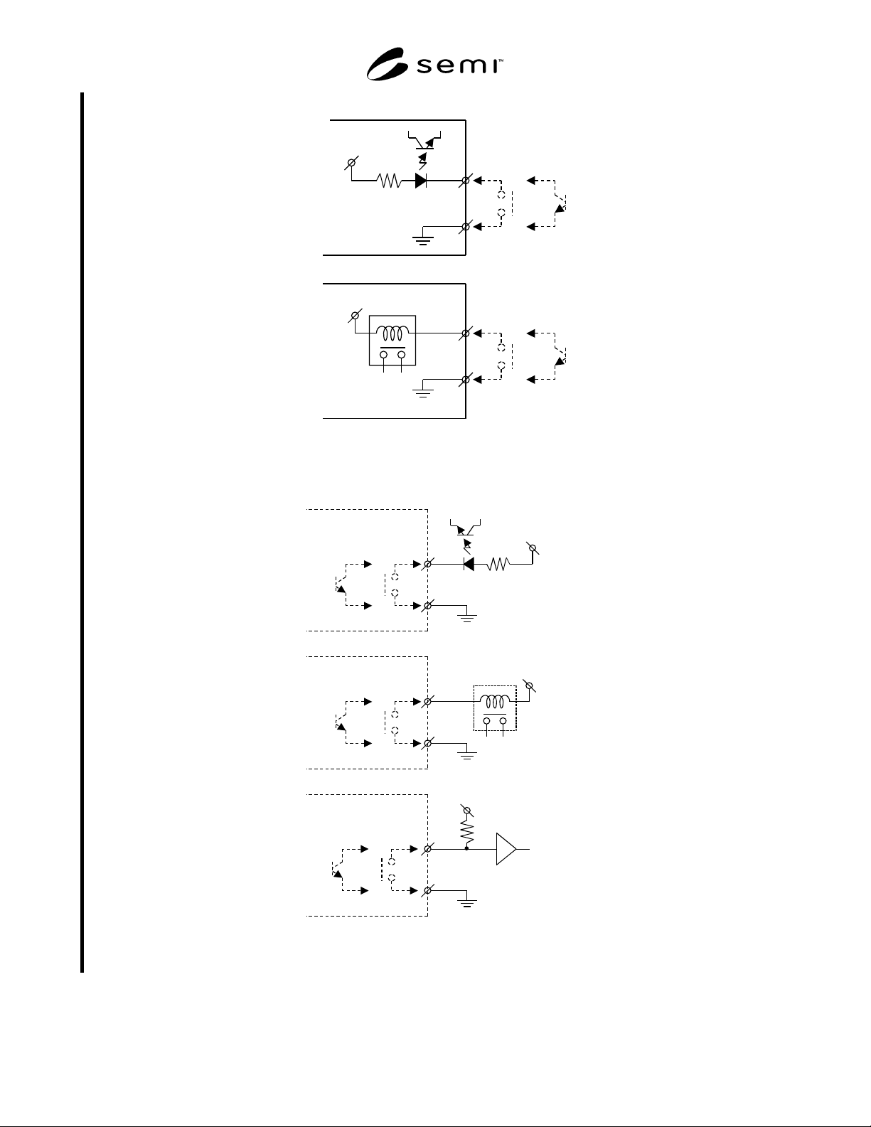
SEMI E74-0301 © SEMI 1998 , 2001 7 DC Voltage DC Voltage Tool TMP (+) (-) (+) (-) TMP Tool b ) a ) Figure 5 Schematic Exa mple of TMP Input Signals Tool TMP DC Voltage DC Voltage DC Volt age (+) (-) (+) (-) (+) (-) a ) T…
SEMI E74-0301 © SEMI 1998, 2001 6
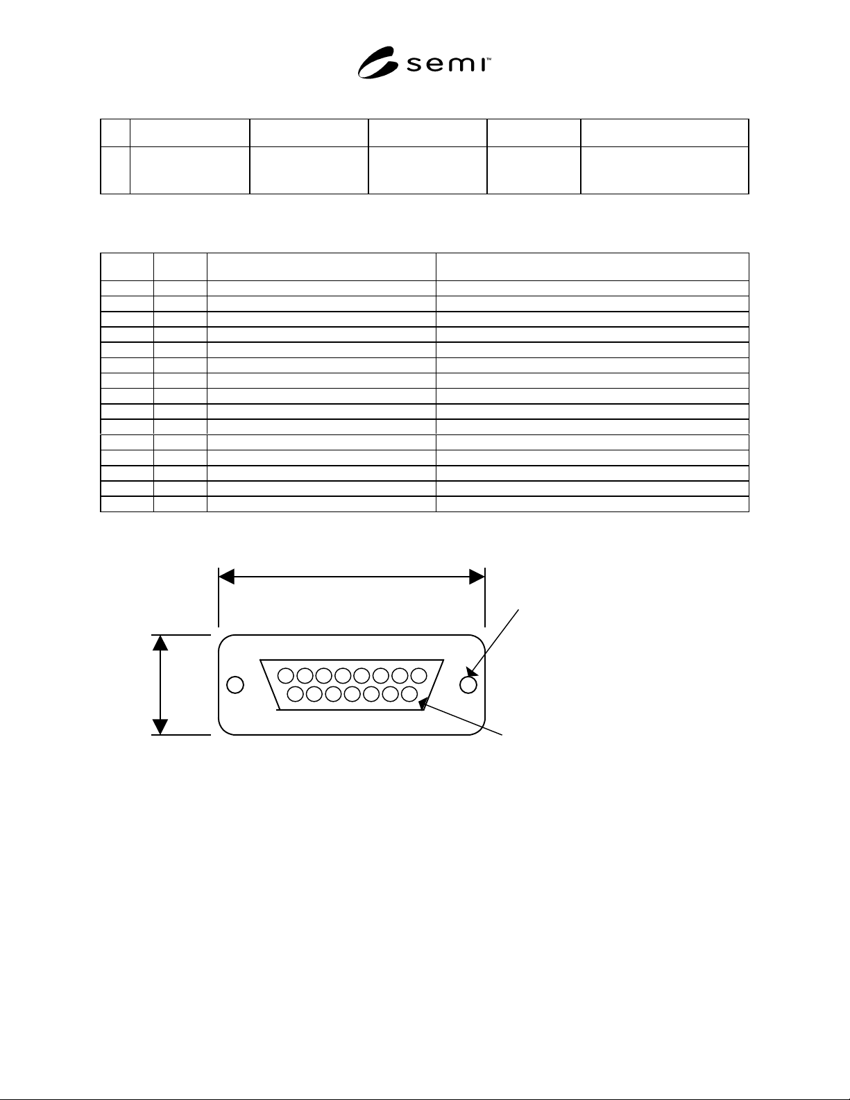
Table 6 Control Signal Connector (Pump Side)
No. Items Connector Type Referenced Standard Pin Assignments Remarks
1 Control and running
status signals
15 pin
D sub-miniature
Female receptacle
See Table 7 and
Figure 4
(See Related Documents for an
example of the specification for
this connector type.)
Table 7 Pin Assignment for Control Signal Connector
No. Pin No. Signal item (polarity) Remarks
1 1 Start/Stop input ( + )
22
3 3 Acceleration status ( + )
4 4 Normal status ( + )
5 5 Deceleration status ( + )
6 6 Alarm status ( + )
7 7 Remote/Local status ( + )
88
9 9 Start/Stop input ( - )
10 10
11 11 Acceleration status ( - )
12 12 Normal status ( - )
13 13 Deceleration status ( - )
14 14 Alarm status ( - )
15 15 Remote/Local status ( - )
MAX. 45.1 mm
MAX. 18.0 mm
Screw lock size : M2.6
Contact pin surface : Au
Figure 4
15 pin D sub-Miniature Female Receptacle
SEMI E74-0301 © SEMI 1998, 20017
DC Voltage
DC Voltage
ToolTMP
(+)
(-)
(+)
(-)
TMP Tool
b
)
a
)
Figure 5
Schematic Example of TMP Input Signals
ToolTMP
DC Voltage
DC Voltage
DC Voltage
(+)
(-)
(+)
(-)
(+)
(-)
a
)
ToolTMP
ToolTMP
b
)
c
)
Figure 6
Schematic Example of TMP Output Signals
SEMI E74-0301 © SEMI 1998, 2001 8
6.3 Incoming Power Supply
6.3.1 Table 8 and Table 9 specify the required TMP incoming AC power supply connector and pin assignments.
Table 8 Incoming AC Power Supply Connector (pump side)
No. Items Connector Type Referenced Standard Pin Assignments Remarks
1 Single phase,
200V
AC
− 230V
AC
± 10%
50/60 Hz
Receptacle (male) SEMI S2 See Table 9
Table 9 Pin Assignment for Incoming Power Supply Connector
No. Pin No. Item Remarks
1 1 or A Hot AC
2 2 or B Cold single phase
3maximum or last
pin number in the
connector
Earth/Ground When using a connector that has a special grounding pin
not included in the standard pin arrangement, the last pin
becomes a blank pin. (See Related Documents for an
example of specification for this connector.)
7 Related Documents
NOTE 2: All documents cited will be the latest published versions.
7.1 DIN Standard
2
DIN VDE 0627 — Connectors and plug-and-socket devices; for rated voltages to 1000 V
AC
, up to 1200 V
DC
, and
rated currents up to 500 A for each pole
7.2 Military Standard
3
MIL-PRF-24308 — General Specification for Connectors, Electric, Rectangular, Non-Environmental, Miniature,
Polarized Shell, Rack, and Panel
NOTICE: SEMI makes no warranties or representations as to the suitability of the standards set forth herein for any
particular application. The determination of the suitability of the standard is solely the responsibility of the user.
Users are cautioned to refer to manufacturer’s instructions, product labels, product data sheets, and other relevant
literature respecting any materials mentioned herein. These standards are subject to change without notice.
The user’s attention is called to the possibility that compliance with this standard may require use of copyrighted
material or of an invention covered by patent rights. By publication of this standard, SEMI takes no position
respecting the validity of any patent rights or copyrights asserted in connection with any item mentioned in this
standard. Users of this standard are expressly advised that determination of any such patent rights or copyrights, and
the risk of infringement of such rights, are entirely their own responsibility.
2 Deutsches Institut für Normung e.V., Beuth Verlag GmbH Burggrafenstrasse 4-10, D-10787 Berlin, Germany
3 Military Standards, Naval Publication and Form Center, 5801 Tabor Avenue, Philadelphia, PA 19120