semi合集-English.pdf - 第2606页
SEMI E91-0600 © SEMI 1999 , 2000 11 7.4 Dat a Item Variable T able Table 7 Data Item Variable Table Variable Name Descriptio n Class Format Comments StopUnit Constant whic h speci fie s separation of stop operatio n in p…
SEMI E91-0600 © SEMI 1999, 2000 10
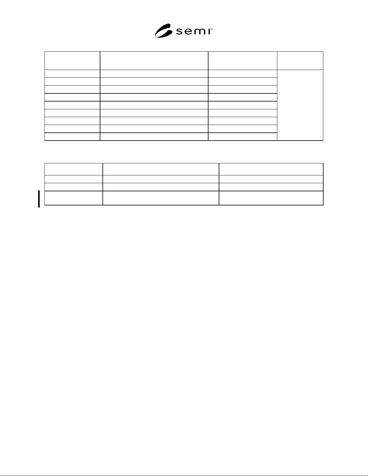
Table 5 Collection Events Required by Prober Job State Transition
Transition Current State New State
Typical Variable
Data
JOB Created Undefined JOB CREATED
JOB Canceled JOB CREATED Undefined
JOB Started JOB CREATED JOB SET UP
Enter Processing JOB SET UP JOB PROCESSING
End Processing JOB PROCESSING Undefined
Start Aborting JOB SET UP, JOB PROCESSING JOB ABORTING
End Aborting JOB ABORTING Undefined
Start Stopping JOB SET UP, JOB PROCESSING JOB STOPPING
End Stopping JOB STOPPING Undefined
EventJobID
Table 6 Other Collection Events
Event Name Contents Typical Variable Data
Wafer Start Wafer processing was started. WaferStartJobID, WaferStartWaferID
Wafer End Wafer processing was completed. WaferEndJobID, WaferEndWaferID
Ready to Receive
Previous Data
Waits for reception of instructed data for wafer. WaitPreDataJobID, WaitPreDataWaferID
7 Data Item Variables
7.1 The purpose of this section is to define the list of
data item variables required by the PSEM. Values of
these variables will be available to the host through
collection event reports and host status queries.
7.2 Requirements
7.2.1 All generic variable data items defined in GEM
are required by all PSEM equipment. Any supplier-
defined variables shall be documented in the same
format used by this document. The following minimum
information is required:
<variable name> Class: <ECV, SV, or DVVAL>
Format: <SML>
Description: <if class=DVVAL, description must
contain statement of when data is
valid>.
<If format = ASCII then a length is
required. It is assumed to be left-
justified unless otherwise noted. >
7.3 Data Types
7.3.1 Equipment Constants (ECVs) can be changed by
the host using S2F15. The operator may be able to
change some values, but the equipment does not change
the values on its own. The value of an equipment
constant may be queried by the host at any time, using
the S2F13/14 transaction. They reside in non-volatile
memory of the equipment. Equipment constants remain
in effect until they are overwritten either by manual
entry or by a NEW EQUIPMENT CONSTANT SEND.
Equipment constants have various uses in PSEM,
including the following:
• Equipment offsets that match the performance of
several pieces of equipment that would otherwise
perform differently due to inherent manufacturing
differences. Examples are home values and motion
axis scaling factors.
• Setting the configuration of the equipment to allow
for different material specifications, equipment
options, material flows, frequency of automatic
functions, etc. Examples are yield check frequency.
• Managing optional machine features. Examples are
constants that tell the system whether optional
features such as automated media stackers are
present and control the configuration and function
of these optional subsystems when they are
present.
7.3.2 Status Variables (SVs) are val id at all times. A
SV may not be changed by the host but may be changed
by the equipment or operator. The value of status
variables may be queried by the host at anytime using
the S1,F3/4 or S6,F19/20 transactions. DVVALs are
variables that are valid only upon the occurrence of
specific collection events. An attempt to read a data
variable at the wrong time will not generate an error,
but the data reported may not have relevant meaning.
SEMI E91-0600 © SEMI 1999, 200011
7.4 Data Item Variable Table
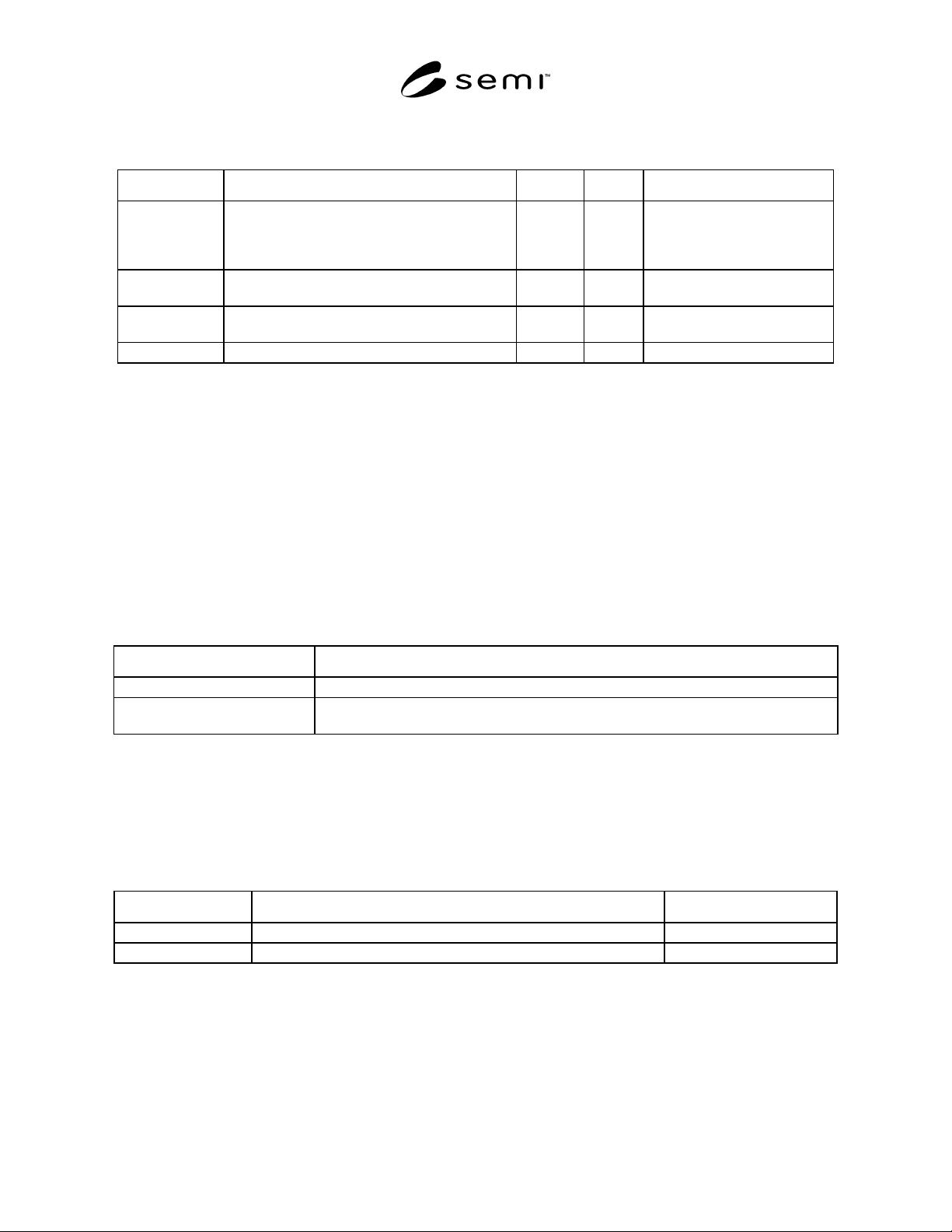
Table 7 Data Item Variable Table
Variable Name Description Class Format Comments
StopUnit Constant which specifies separation of stop
operation in probing.
ECV U1 0=Unit of Die
1=Unit of Wafer
2=Unit of Cassette
3=Unit of Lot
EventJobID Prober Job ID which occurs Prober Job state
transition.
DVVAL A[30] Valid when Prober Job state
transition occurs.
EventJobState Current state of Prober Job whose state changed. DVVAL U2 Valid in event of Prober Job
state transition.
ResultData Processing result in unit of one wafer. DVVAL L[n] Valid only in wafer end event.
8 Process Program Manage ment
8.1 PSEM explains how to specify a process program for the prober and the process program control between the
host and prober.
8.2 Process Program Requirements
8.2.1 The PSEM requires that the G EM capability of process program management be fully supported for this class
of prober.
8.3 Process Program
8.3.1 The process program of the prober consists of the main process program and two or more sub process
programs that are referred to by the main process program.
Table 8 Kinds and Descriptions of Process Programs
Kind Description
Product type master record Master process program for processing.
Sub-parameter record Sub-process program for processing.
Various kinds of parameter records that consist main process program for processing.
8.3.2 These process programs are controlled by the prober with grouped into different categories according to
application purposes and structures. The prober defines PPID with “structure class name/class name/process
program record name.” The number of PPID digits is defined by an equipment supplier. If the number of the digits
is less than a default value, left-justify and fill in space after PPID. Do not use space at some midpoint in PPID. At
present, the prober practically uses the structure class name and class name as shown in the table given below.
Table 9 How to Operate Class Name and Structural Class Name
Classification Operation Remarks
Structural class name Class name indicating major classification of process program record. Defined by supplier.
Class name Class name indicating attribute of process program record. Defined by supplier.
8.4 Master Process Program Reco rd
8.4.1 The master process program re cord is a plain text (ASCII) record like below:
DEVICE:xxxxxxxx
WAFER_SIZE:xx
DIE_SIZE:xxxxxx,xxxxxx
SEMI E91-0600 © SEMI 1999, 2000 12
.........
PARAM_RECORD00:structure class name/class name/process program record name
.........
PARAM_RECORDnn:structure class name/class name/process program record name
8.4.1.1 Each line has a structure:
TAG + ":" + parameter(s) + line terminator
8.4.1.2 The line terminator is some of CR+LF (0x0d0a), CR (0x0d), LF (0x0a).
8.4.1.3 Specific parameters of equipment supplier may be put between "HOT_CHUCK_TOLE" and
"PARAM_FILE00".
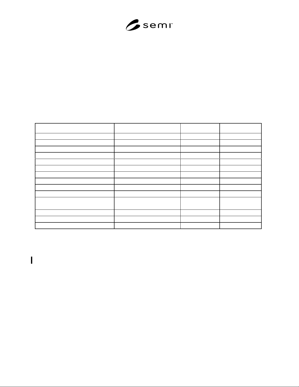
Table 10 Tag Parameters in Master Process Program
Tag Description Format Unit
PRODID Product name (i.e., Device type) A[1,24] -
WAFER_SIZE Wafer size A[1,3] mm
DIE_SIZE_X Die size X A[1,6] micron
DIE_SIZE_Y Die size Y A[1,6] micron
MULTI_DIE Multi probing number A[1,3] -
REFERENCE_DIE_COORD_X Reference die coordinator X A[1,4] -
REFERENCE_DIE_COORD_Y Reference die coordinator Y A[1,4] -
OVER_DRIVE Over drive value A[1,4] micron
FLAT_ANGLE Flat orientation A[1,3] degree
FLAT_TYPE FLAT or NOTCH A[1,5] -
HOT_CHUCK Flag of hot chuck usage A[2,3]
“ON” or “OFF”
-
HOT_CHUCK_TEMP Hot chuck temperature A[1,4] Celsius
HOT_CHUCK_TOLE Hot chuck tolerance A[1,3] Celsius
PARAM_RECORDnn Sub-parameter record nn A[ ] -
9 Map Data
9.1 This section defines handling o f map data in the PSEM equipment. The contents of map data are not defined
here. The specification in this section is provisional. This will be revised in the near future.
9.2 Use of Map Data
9.2.1 Map data is divided into two groups: result data which is reported to the host when processing of each wafer
is completed and instruction data which is instructed by the host in a unit of wafer at the time of re-inspection or
marking.
9.3 Structure of Map Data
9.3.1 The map data has a list structu re and the result data is defined by class <DVVAL> and the instruction data is
defined by <CEPVAL>.
9.3.1.1 Example:
<ResultData>
L,n
1. <Data
1
>