semi合集-English.pdf - 第6852页
SEMI S2-0703a E © SEMI 1991, 2004 81 R14-6.2.18 safety PLC — a programmable logi c controller and associated I/O, certifie d as having the necessary safety integrity to ex ecute the safety-related function. R14-6.2.19 sa…

SEMI S2-0703a
E
© SEMI 1991, 2004 80
R14-6.1.2 CAT. 4 — Category 4 (according to ISO
13859-1)
R14-6.1.3 CPU — Central Processing Unit
R14-6.1.4 EMO — Emergency Off
R14-6.1.5 EUC — Equipment Under Control
R14-6.1.6 FD — Field Device
R14-6.1.7 FECS — Fail-to-Safe Equipment Control
System
R14-6.1.8 GUI — Graphical User Interface
R14-6.1.9 I/O — Input/Output
R14-6.1.10 IFD — Intelligent Field Device
R14-6.1.11 ISFD — Intelligent Safety Field Device
R14-6.1.12 PLC — Programmable Logic Controller
R14-6.1.13 SIL — Safety Integrity Level (according to
IEC 61508)
R14-6.1.14 SRM — Safety Relay Module
R14-6.2 Definitions
R14-6.2.1 certified — Evaluated and approved for use
in a particular intended function in conformance with a
recognized standard by an accredited testing laboratory
(ATL).
NOTE 1: See SEMI S2 for definition of ATL.
R14-6.2.2 combined I/O — I/O systems of an FECS in
which non-safety-related and safety-related signal
modules are combined. (see Figure R14-2).
R14-6.2.3 common cause failure — failure, which is
the result of one or more events, causing coincident
failures of two or more separate channels in a multiple
channel system, leading to system failure.
R14-6.2.4 distributed I/O — input/output modules for
sensors and actuators interfacing to a network.
R14-6.2.5 electrical/electronic/programmable
electronic (adj.) — based on electrical OR electronic
OR programmable electronic technology.
NOTE 6: The term above is intended to cover any and all
devices or systems operating on electrical principles.
R14-6.2.6 Fail-to-safe equipment control system — A
programmable system of control circuits designed and
implemented for safety-related functions in accordance
with internationally recognized standards such as ISO
13849-1 (EN 954-1) or IEC 61508. These systems (e.g.
safety PLC, safety-related I/O modules) diagnose
internal and external faults and react upon detected
faults in a controlled manner in order to bring the
equipment to a safe state.
R14-6.2.7 field device — sensors and actuators such as
valves (electrical or pneumatic), temperature sensors,
proximity switches, pumps, motors etc.
R14-6.2.8 functional safety — The overall safety
design related to the EUC and the EUC control system.
Effective functional safety includes the correct
functioning of the electrical, electronic, or
programmable-electronic safety-related systems; or on
other-technology safety-related systems and may
include risk reduction measures.
R14-6.2.9 industrial controller — general term for
controller-technology, which includes PLC and PC-
based technology.
R14-6.2.10 intelligent field device — sensors and
actuators that use local intelligence to perform
functions such as communication, diagnosis and
interfacing to a network.
R14-6.2.11 network — general term for bus
technology, which includes field bus technology used in
control applications.
R14-6.2.12 programmable logic controller —
microprocessor based controller for sequential control;
the control logic of which can be changed through a
programming device connected to the controller, e.g.
programming panel, host computer, handheld terminal,
either directly or remotely through a network.
R14-6.2.13 random hardware failure — failure,
occurring at a random time, which results from one or
more of the possible degradation mechanisms in the
hardware.
R14-6.2.14 safety function — function to be
implemented by an electrical or electronic or
programmable electronic safety-related system, other
technology safety-related system or external risk
reduction facilities, which is intended to achieve or
maintain a safe state for the EUC, in respect of a
specific hazardous event.
R14-6.2.15 safety integrity — probability of a safety-
related system satisfactorily performing the required
safety functions under all the stated conditions within a
stated period of time.
R14-6.2.16 safety integrity level (SIL) — discrete level
(one out of a possible four) for specifying the safety
integrity requirements of the safety functions to be
allocated to the electrical or electronic or programmable
electronic safety-related systems, where safety integrity
level 4 has the highest level of safety integrity and
safety integrity level 1 has the lowest.
R14-6.2.17
safety network — a network certified for
safety applications (this can also be a subpart of a
standard network).
SEMI S2-0703a
E
© SEMI 1991, 2004 81
R14-6.2.18 safety PLC — a programmable logic
controller and associated I/O, certified as having the
necessary safety integrity to execute the safety-related
function.
R14-6.2.19 safety relay (SR) —- A positive or force-
guided relay, that is used in safety relay modules
(SRMs) to achieve a fail-to-safe circuit.
R14-6.2.20 safety relay module (SRM) — redundant
self monitoring electro-mechanical/ solid state device
certified for use in safety applications
R14-6.2.21 safety-related I/O modules —I/O modules
capable of diagnosing internal and external faults and
configured to be redundant. (e.g., a second shutdown
path is included for output-circuits).
R14-6.2.22 safety-related programmable system —
systems designed and implemented for safety functions
in accordance with ISO 13849 or IEC 61508. These
system types (e.g. safety PLC, safety-related I/O
modules) can diagnose internal and external faults and
can react upon detected faults in a controlled manner.
R14-6.2.23 safety requirements specification —
specification containing all the requirements of the
safety functions that have to be performed by the
safety-related systems.
R14-6.2.24 solid state electronics — designation used
to describe devices and circuits fabricated from solid
materials such as semiconductors, ferrites, or thin films
as distinct from devices and circuits making use of
electromechanical technology, e.g. solid state relay,
micro controller.
R14-6.2.25 systematic failure — failure related in a
deterministic way to a certain cause, which can only be
eliminated by a modification of the design or of the
manufacturing process, operational procedures,
documentation or other relevant factors.
R14-7 State-of-the-Art Safety Control System
— Comprised of Solid State Electronics
R14-7.1 Failure to perform normal function (for
example a failure of a computer or its software) may
cause economic loss, but is not necessarily a safety
issue. However, failure of a safety-related component
to perform its safety function could result in a
hazardous condition. A fail-to-safe system should be
designed in a manner to ensure that failures do not
result in a hazardous situation. It is therefore important
to perform a system risk assessment to determine
safety-related functions and the - safety performance
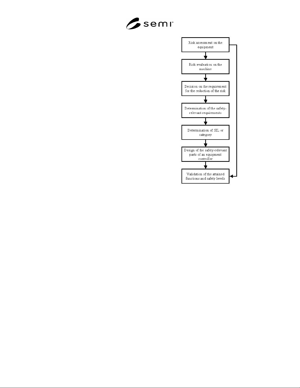
required. The process outlined in following figure
should be followed.
Figure R14-1
Roadmap to Risk Assessment and System Design
R14-7.2 Safety Interlocks — Semiconductor
manufacturing equipment requires the use of fast,
reliable and efficient means of safety interlocking.
Important issues concerning complex machine
architectures include availability and diagnostic
capabilities for quick troubleshooting.
R14-7.2.1 A FECS should, even in the case of failure,
maintain a safe state of the EUC. Therefore, a FECS is
able to detect faults and cause the system to go to a safe
state. A properly designed FECS – using methods such
as self-monitoring for fault detection and subsequent
well defined reaction – can offer high availability and
diagnostics.
R14-7.2.2 Section 11.6 of SEMI S2 (including
exceptions and notes) indicates a preference for
electromechanical devices and components, and gives
guidance on their use. However, non-
electromechanical devices and components are
permitted and they can provide necessary risk reduction
while maintaining safety performance. Section 11.6,
Note 26 of SEMI S2, suggests some tools for
investigation of suitability for use. Additionally, IEC
61508, ANSI/ISA-SP84.01, and ISO 13849-1 (EN 954-
1) provide guidance on the safety system design,

SEMI S2-0703a
E
© SEMI 1991, 2004 82
assessment and maintenance of suitable control
systems.
R14-7.2.3 The usage conditions and safety
performance should be determined by the finding of a
risk assessment as described in SEMI S10. Risk
assessment results can then be used to define
appropriate SIL levels and Categories.
NOTE 7:Emergency Off — Section 12.2.2 of SEMI S2 states
that the EMO system should consist of electromechanical
components. The exceptions give guidance to the design of
EMO circuits using alternative technologies. Regional,
national or industry standards may have additional
requirements (e.g., USA: ANSI/NFPA 79, Europe: EN
60204-1).
R14-7.2.4 Any deviation from the risk level of
electromechanical devices must be carefully evaluated
(see Section 8 of SEMI S2).
R14-7.2.5 Compliance with Section 12 of SEMI S2,
emergency shutdown will depend on the risk
assessment allowed in Section 8.3.11 of SEMI S2.
R14-7.3 Software and Programming
R14-7.3.1 The application software or function blocks
have to be verified before being used in an FECS. The
automation supplier usually provides a range of
approved software blocks.
R14-7.3.2 Access for programming of safety-related
functions should be restricted within the FECS to
trained people.
R14-7.3.3 To program or modify safety-related
programs or parts of it, specially trained or qualified
personnel are required. Any changes must be
documented and stored within the file history.
R14-8 Philosophy and General Concept
R14-8.1 Introduction — An automated machine
system mainly comprises components such as industrial
controller, drives, I/O etc. The level of safety
performance of equipment can differ depending on the
particular application of FECS. However, irrespective
of the particular application, the FECS always
comprises a series of sensors, logic elements and
actuators for safe shutdown or a motion into a safe and
stable machine state.
R14-8.1.1 The term FECS according to IEC 61508 Part
2, is equivalent to the terms SIS (safety instrumented
system) or SRS (safety related system) in other
application areas. The examples in this Related
Information show some possible architectures of the
logic system. Sensors, final elements and software are
discussed in this Related Information. Application
handbooks from automation suppliers provide users
with valuable information on how to use these
components in order to achieve a fail-to-safe,
equipment control system.
R14-8.1.2 For traditional semiconductor equipment,
non-safety-related and safety-related technology, are
separated. In many cases non-safety-related and safety-
related technology are linked, so that signals
representing diagnostics, enable, and feedback can be
exchanged.
R14-8.1.3 Main Characteristics of Architecture
Concepts
1. Fail-to-safe equipment control system with
conventional hardwired safety technology.
2. Fail-to-safe equipment control system with
separation between fail-to-safe and standard
network technology.
3. Fail-to-safe equipment control systems with
combined network technology for transmission
of fail-to-safe and standard data on a single
medium.
4. Redundancy can be used in all concepts to
increase availability. Different redundancy
concepts are in use (see R14-Section 9).
5. Visualization on the standard control part and
on the fail-to-safe part can be realized with
various interfaces on the standard part and on
the fail-to-safe part.
R14-8.2 Design of Architecture and Components
R14-8.2.1 Possible Application Areas
1. Semiconductor manufacturing industry
2. Guarding of people, machines, environment
and industrial processes
Emergency stop functions,
Emergency off functions,
Emergency shutdown functions,
Light gates,
Guard doors,
Scanners,
Motion control with safety functions,
Motor control with safety functions,
Process valves with safety functions, and
Process monitoring using safety-related interlocks.
R14-8.2.2 Safety-related Equipment Control System —
The design of FECS should be carried out in
accordance with IEC 61508 and applicable parts of the
other referenced standards. The safety controller is
used to control (open-loop) processes that can