semi合集-English.pdf - 第1411页
SEMI E30-1103 © SEMI 1992, 2003 85 Table A .3 Alarm Example s Per Equipment Configuration Subsystem Alarm Description ALID Trigge r Reset Operator Equipment Material Mainframe Power Supply Overvoltage Voltage supply over…

SEMI E30-1103 © SEMI 1992, 2003
84
The host configures the equipment to monitor specific
variables and to send event reports when variables
transition between monitoring zones.
A1.4 Processing
A1.4.1 Start Process Executing The host or
operator issues a command to start.
A1.4.2 Equipment Signals End of Run When
process execution is completed, the equipment
generates events. If any of the events are enabled, they
will be sent as event reports.
A1.5 Post-Processing The equipment has
completed processing material. It now makes the
material available to the operator or material handling
system for removal. The equipment signals the host that
it is available for more work.
A1.5.1 Material Unload Material is unloaded from
the equipment by an operator or material handling
system.
A.2 Equipment Front Panel
In the GEM standard, several requirements are stated
that involve the display or input of information at the
equipment front panel. The “equipment front panel”
refers to an area on the equipment that is available to
the operator under normal use (i.e., without removing
maintenance access panels). This may include a CRT
display, keyboard, switches, and lights.
This application note provides some guidance for
implementation of the GEM front panel capabilities. All
of these requirements map directly to state models and
capabilities defined in Sections 3 and 4. All capabilities
may be implemented in either hardware (buttons,
switches, lights) or in a software/CRT equivalent.
A2.1 Displays and Indicators The intent of various
displays is to inform the operator of either the current
state of the equipment or of a recent change of state (or
both). Therefore, it is most useful if these displays are
continuously visible and easily recognized at a distance.
Required displays/indicators include:
Communications State: This means that three distinct
states must be represented: DISABLED,
ENABLED/NOT COMMUNICATING, and
ENABLED/COMMUNICATING.
Terminal Services: An “New Host Message” indicator
must be supplied.
A2.2 Switches/Buttons Note that discrete switches
also contain information for the user. However, these
tend to represent the desired states of the operator/user.
The equipment’s response to a change of a switch may
not be instantaneous. Still, the current position of
switches should be available to the operator.
It may be appropriate to limit the access to some
switches and buttons. This might be done via any of the
standard methods, keys, passwords, combinations, etc.
This is especially true for system default switches that
would not often be changed. Required switches/buttons
include:
Communications State System Default: In what
communications state should the equipment be when
system initialization is complete? The choices are
DISABLED and ENABLED.
Communications State Selector: This is a toggle or
button that will initiate a transition from ENABLED to
DISABLED or vice versa.
Message Recognition Button: This button is used to
initiate an event message to the host which indicates
that the “New Host Message” has been read. This
button should function only when the New Host
Message Indicator is activated and when the received
message is displayed in the terminal display.
A.3 Examples of Equipment Alarms
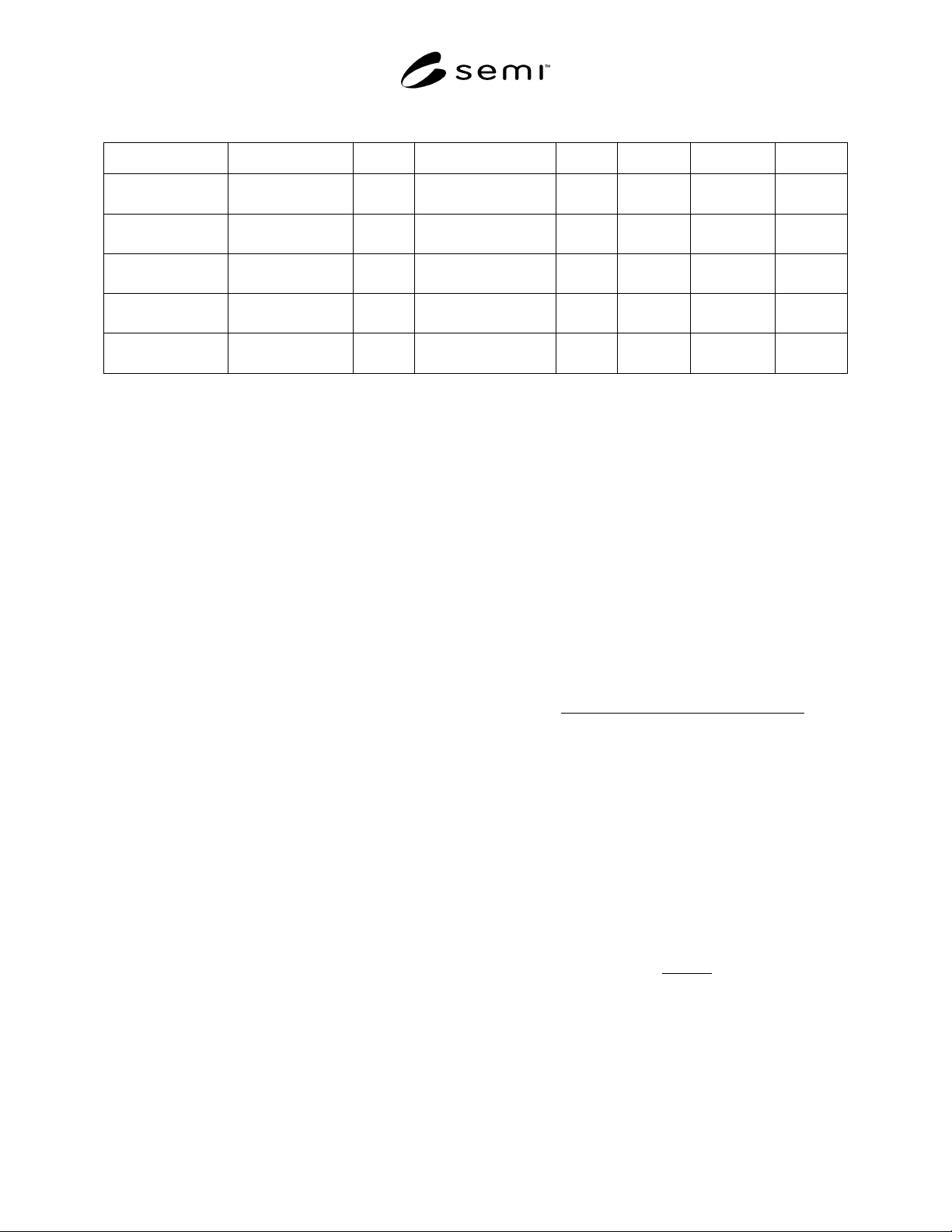
Table A.3 provides alarm examples pertaining to
various configurational aspects of equipment.
NOTE: It is important to stress that these are just
examples intended to illustrate that alarms pertain to
situations in which there exists a potential for
exceeding physical safety limits associated with people,
equipment, and material being processed as per the
GEM definition of an alarm.
NOTE: The alarm capability is intended as an addition
to standard safety alarms (e.g., lights, horns). There is
no intent to replace direct operator reaction to such
problems. Nor is there the expectation that the host can
necessarily prevent or directly address such alarms.
An actual machine shall have an associated set of
alarms defined by the manufacturer that pertains to its
specific configuration and design. The equipment
manufacturer is responsible for supplying
documentation associated with these alarm definitions.
SEMI E30-1103 © SEMI 1992, 2003
85
Table A.3 Alarm Examples Per Equipment Configuration
Subsystem Alarm Description ALID Trigger Reset Operator Equipment Material
Mainframe Power
Supply
Overvoltage Voltage supply over
maximum limit
X
Undervoltage Voltage supply under
minimum limit
X
Internal Power
Distribution Bus
AC Low AC under minimum
limit
X X
Cooling System Overtemp Temperature over
maximum
X X
Pressure Low Pressure below
minimum
X
Subsystem The subsystem of the equipment to which the alarm is related
Alarm Description Description of the alarm
ALID The Alarm ID as specified by SECS-II
Trigger Text description of what caused the alarm
Reset Description of how to resolve the alarm condition
Affected Who or what is affected by the alarm trigger: Operator, Equipment, and Material
A.4 Trace Data Collection Example
This example shows an implementation of the Trace
Data Collection capability defined in Section 4.2.3.
S2,F23 sent by host:
TRID = ABCD
DSPER = 000100 (One minute per
period)
TOTSMP = 9
REPGSZ = 3
SVID1 = Temperature
SVID2 = Relative humidity
S6,F1 looks like this (starting at time 1 a.m.):
1st transmission <L,4>
1. ABCD (trace ID)
2. 3 (last sample of the
transmission)
3. 88 5 01 01 03 00
Year Month Day Hour Min Sec
4. <L, n> n = 2 SVID‘s x REPGSZ of
3 = 2 x 3 = 6
72 (temperature)
0.29 (relative humidity)
73 (temp.)
0.30 (r.h.)
71 (temp.)
0.30 (r.h.)
2nd transmission <L,4>
1. ABCD
2. 6
3. 88 05 01 01 06
00
hr min
4. <L,6>
73
0.31
71
0.32
71
0.31
SEMI E30-1103 © SEMI 1992, 2003
86
3rd and last transmission <L,4>
1. ABCD
2. 9
3. 88 05 01 01 09
00
hr min
4. <L,6>
71
0.30
72
0.30
71
0.31
A.5 Harel Notation
Harel’s statecharts extend traditional state-transition
diagrams with several additional concepts, most
important of which are hierarchy and concurrence.
Statecharts depict the behavior of a system by showing
states it may take, events that prompt a change of state,
and the composition of states. What follows is a very
brief description of the symbols defined for use and
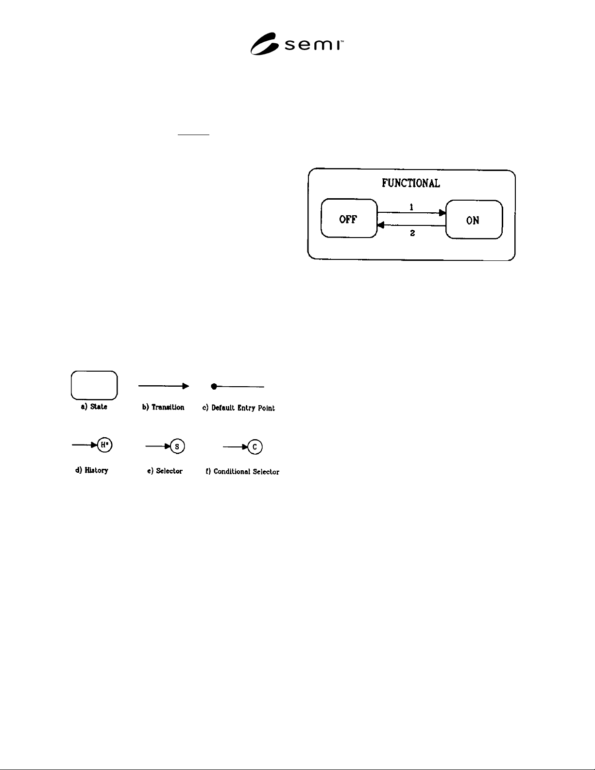
how these are useful to describe a system. See Figure
A.5.1 for the basic notational symbols.
Figure A.5.1
Harel Statechart Symbols
States are represented by rounded boxes. A state
transition is shown graphically with a line from the old
state terminating with the arrow symbol at the new
state. Transitions are unidirectional-while the reverse
transition may be possible, it is considered a different
transition with different conditions for initiation and
different resultant actions.
States may be subdivided into substates to facilitate
more concise definition of behavior. Thus, a hierarchy
is defined whereby any state may be a substate of some
parent state and in turn be the parent of its own
substates. Substates must be one of two types, termed
AND substates and OR substates.
A parent maybe divided into two or more OR substates
of which one and only one is the active substate at any
time. The accepted term for this exclusivity is XOR.
Figure A.5.2 gives an example of a simple case of OR
substates. In this example, some system (perhaps a
motor) has a state named FUNCTIONAL. When the
motor is FUNCTIONAL, it may be either ON or OFF,
but never both.
Figure A.5.2
Example of OR Substates
Another way of dividing a parent state corresponds
roughly to subsystems. These AND substates represent
parallelism, such that every AND substate of an active
parent state is considered active. Harel also uses the
term “Orthogonal Component” to refer to AND
substates. However, these parallel substates tend to be
highly interactive and interdependent. For this reason,
the word orthogonal is considered confusing and has
been excluded from use in this document. Figure A.5.3
shows an example of AND substates representing (in
part) an automobile. Note the convention of attaching
the name of the parent state AUTOMOBILE to the
outside of the state in a small box. The substates shown
are independent components and may have their own
substates (of either the AND or OR type):
— LIGHTS may be ON or OFF;
— DOOR may be OPEN or CLOSED;
— ENGINE is constructed of components such as
pumps, pistons, carburetor, etc.
Exiting one of a set of AND substates requires the exit
of all others. In some cases, a transition arrow will be
shown from only one of the substates with the others
implied.