semi合集-English.pdf - 第6137页
SEMI G29-1296 E © SEMI 1986, 2002 1 SEMI G29-1296 E TEST METHOD FOR TRACE CO NTAMINANTS IN MOLDING COMPOUNDS E This document was editorially modifi ed in September 2002. Changes were made to Section 5.4 to correct a typo…
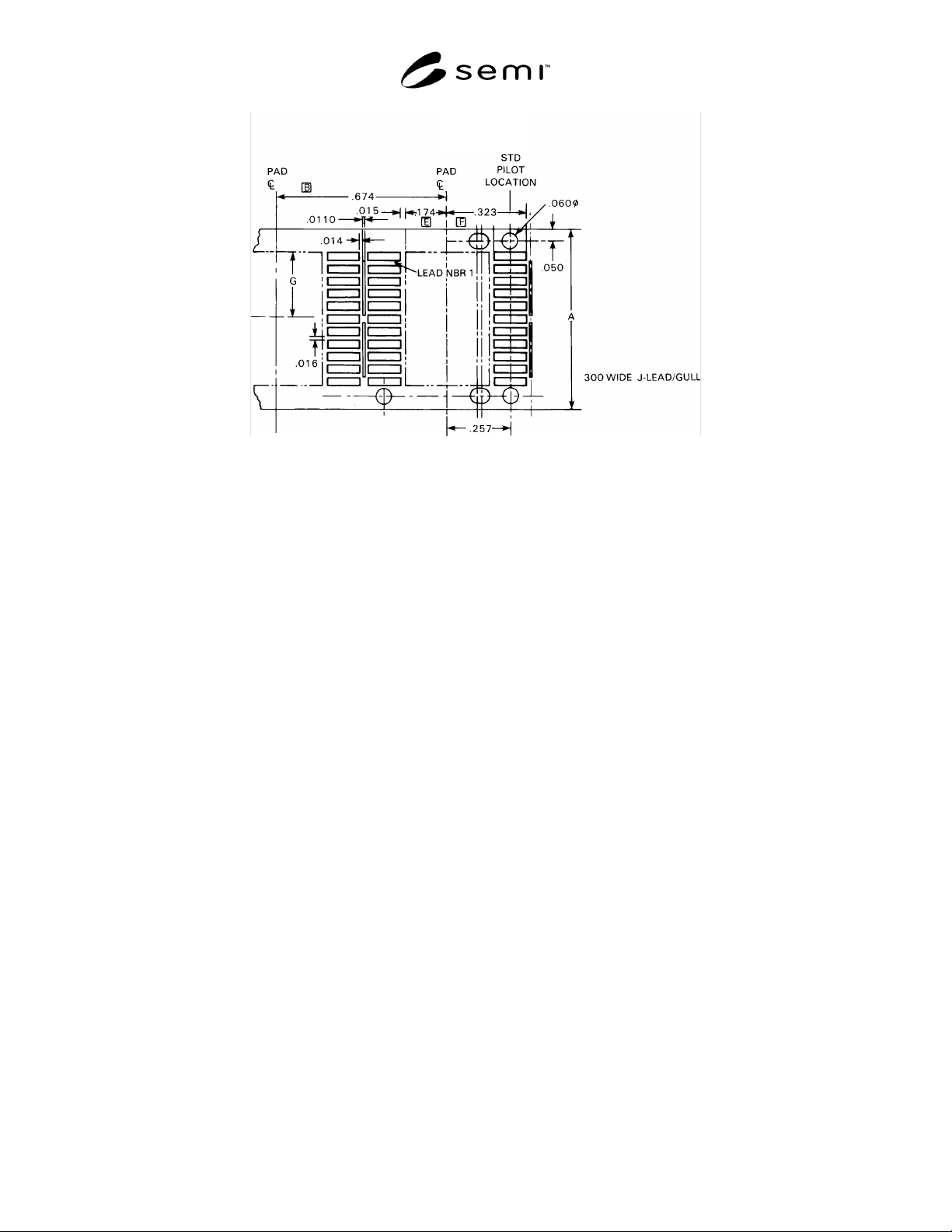
SEMI G28-0997 © SEMI 1986, 1997 8
Figure 8
S.O. Leadframe
NOTICE: These standards do not purport to address safety issues, if any, associated with their use. It is the
responsibility of the user of these standards to establish appropriate safety and health practices and determine the
applicability of regulatory limitations prior to use. SEMI makes no warranties or representations as to the suitability
of the standards set forth herein for any particular application. The determination of the suitability of the standard is
solely the responsibility of the user. Users are cautioned to refer to manufacturer’s instructions, product labels,
product data sheets, and other relevant literature respecting any materials mentioned herein. These standards are
subject to change without notice.
The user’s attention is called to the possibility that compliance with this standard may require use of copyrighted
material or of an invention covered by patent rights. By publication of this standard, SEMI takes no position
respecting the validity of any patent rights or copyrights asserted in connection with any item mentioned in this
standard. Users of this standard are expressly advised that determination of any such patent rights or copyrights, and
the risk of infringement of such rights, are entirely their own responsibility.
Copyright by SEMI® (Semiconductor Equipment and Materials
International), 3081 Zanker Road, San Jose, CA 95134. Reproduction o
f
the contents in whole or in part is forbidden without express written
consent of SEMI.

SEMI G29-1296
E
© SEMI 1986, 2002 1
SEMI G29-1296
E
TEST METHOD FOR TRACE CONTAMINANTS IN MOLDING
COMPOUNDS
E
This document was editorially modified in September 2002. Changes were made to Section 5.4 to correct a
typographical error.
1 Purpose
1.1 This specification defines the test method for
determination of extractable trace contaminants in
molding compound.
2 Scope
2.1 This test method is suitable for all molding
compound materials and may be used by supplier and
customers to determine the trace contaminants in
molding compound.
2.2 This standard does not purport to address safety
issues, if any, associated with its use. It is the
responsibility of the users of this standard to establish
appropriate safety health practices and determine the
applicability or regulatory limitations prior to use.
3 Referenced Documents
3.1 ASTM Documents
1
ASTM D 1193 — Specification for Reagent Water
ASTM D 4327 — Anions in Water by Ion
Chromatography
4 Method Summary
4.1 Plastic molding compound material is molded,
ground to a defined mesh size, and placed into a sealed
extraction vessel with de-ionized water. Extraction is
carried out at 120 ± 2° C for 48 hours. The extract is
analyzed for both anionic and cationic impurities.
5 Sample Preparation
5.1 Samples of molding compound materials may be
obtained from either standard molding operations, or
prepared in the laboratory.
5.1.1 Samples from molding operations may include
mold runners post-cured according to manufacturer’s
recommendations.
5.1.2 To secure a sample in the laboratory, spread a
thin layer of uncured compound in a dedicated clean
1 American Society for Testing and Materials, 100 Barr Harbor
Drive, West Conshohocken, Pennsylvania 19428-2959, USA.
Telephone: 610.832.9585, Fax: 610.832.9555 Website:
www.astm.org
teflon-coated container. Cure and post-cure the
compound material according to manufacturer’s
recommendations.
5.2 Crush the cured material using a suitable grinding
apparatus, such as Spex mixer-mill No. 8000, or
equivalent.
NOTE 1: The grinder used must not generate excess localized
heat, or else sample decomposition and erroneous results may
be generated.
NOTE 2: Addition of liquid nitrogen is a suitable method for
eliminating undesirable thermal decomposition during
grinding.
5.3 Remove the ground compound and sieve it. Collect
for analysis the portion which passes through a 40 mesh
size, but is retained on a 100 mesh size screen. This
particle size is best suited for adequate extraction of
impurities.
5.4 Weigh 10 ± 0.1 grams of the powdered material
and place in an extraction vessel. Parr bombs with
teflon liners are suitable extraction vessels. Add 100 ml
de-ionized water. Prepare blank extraction vessel by
processing it in the same manner as your sample.
Weigh the sealed bombs and record their weights. Place
the sealed bottles on their sides in an oven at 120 ± 2° C
for forty-eight (48) hours.
NOTE 3: Certain compounds may require addition of reagent
grade methanol 10% (V:V) to enhance wetting.
5.5 At the completion of forty-eight (48) hours of
extraction, allow the bombs to cool to room
temperature and reweigh. If the weight loss exceeds 0.5
grams the sample should not be used for analysis.
Portion of this extract may be used to generate pH and
conductivity data. Anion analysis may be performed
using ion chromatography or specific ion electrodes.
Cation analysis may be conducted using atomic
absorption, plasma spectrometry, or ion
chromatography.
NOTE 4: It is important to avoid contamination with
particulate matter in the extract used for the analysis by AA,
ICAP, or IC. This procedure addresses determination of
extractive species only.

SEMI G29-1296
E
© SEMI 1986, 2002 2
6 Instrumentation Techniques
6.1 Measurement of Conductivity
6.1.1 Apparatus — Conductivity Meter Model RC1682
with microconductivity cell, industrial instruments, or
equivalent.
6.1.2 Measurement — Measure conductivity of the
sample and black solutions. Calculate the specific
conductance of sample using the following equation:
L
s
= (L
e
- L
b
) K
L
s
- Specific conductance, S cm
-1
L
e
- Conductance of extract, S
L
b
- Conductance of the blank
K - Conductivity cell constant
6.2 Measurement of pH
6.2.1 Apparatus
6.2.1.1 pH meter (Orion, Model 601, or equivalent)
6.2.1.2 pH standard solutions
6.2.2 Measurement — Adjust pH meter indicator by
using standard solutions. Remove the electrodes with
de-ionized water and dry with clean filter paper. Place
the electrodes into the molding compound extract.
Allow the meter to equilibrate. Record the pH value.
6.3 Ion Specific Electrodes — Ion-specific electrodes
may be used for the determination of chloride, bromide,
sulfate, and phosphate. A separate specific electrode for
each ion is required and, in some instances, a reference
electrode may be necessary to complete the test.
Individual standards are needed for each ion tested.
Methodology recommended by the manufacturer for
each ion specific electrode should be closely followed.
Measured concentrations corrected for blank value
should be compared to the known standards in the
range 0.1–100 ppm. Chloride and bromide are usually
determined, using a solid state single electrode.
Determination of sulfate and phosphate ions may
require use of additional buffers and a titration.
6.4 Determination of Sodium, Potassium, and
Antimony Using Atomic Absorption
6.4.1 Apparatus — Atomic absorption
spectrophotometer.
6.4.2 Standard Solutions
6.4.2.1 Sodium standard solutions 0.1, 0.2, 0.4, 0.6,
0.8, 1.0 ppm.
6.4.2.2 Potassium standard solutions 0.1, 0.2, 0.4, 0.6,
0.8, 1.0 ppm.
6.4.2.3 Antimony standard solution 0.1, 0.2, 0.4, 0.6,
0.8, 1.0 ppm.
6.4.3 Measurement — Set up instrument according to
manufacturer’s recommendation. Analyze water extract
based on the calibration curve prepared using standard
solutions to obtain concentration of ion of interest.
6.4.4 Calculation
6.5 Determination of Chloride, Bromide, Phosphate,
Sulfate, Sodium, and Potassium by Ion
Chromatography
6.5.1 Method Principle — Ion chromatography is a
form of liquid chromatography used in the separation
and quantitation of ions. A filtered aliquot of sample is
injected into an Ion chromatograph. The sample is
pumped by the eluent stream through two (2) different
ion exchange columns: a guard column, which serves to
protect the separator column from residual particulate
matter and retain certain organics, and the separator
column, the primary function of which is to separate
analyzed ions based on their affinity for the exchange
sites of the resin. Both guard column and the separator
column are packed with identical low capacity anion
exchanger (anion analysis) or cation exchange (cation
analysis). The separated ionic species then pass to a
detector module consisting of a chemical suppressor
device and a conductivity cell. The suppressor device is
used to reduce background conductivity of the eluent to
a low, or negligible level, and convert analyte anions
into their acid form or analyte cations into their
hydroxide form. Thus, separated and modified ionic
species are detected using an electrical conductivity
cell. Anions are identified based on their retention time
compared to the known standards. Quantitation is
accomplished by measuring the peak height or area, and
comparing it to a calibration curve generated from
known standards.
NOTE 5: For recommended practice for ion chromatography
analyses, see instrument manufacturer’s literature and ASTM
D 4327.
6.5.2 Interferences
6.5.2.1 High levels of organic acids may be present in
molding compound extracts. This may interfere with
inorganic anion analysis. Two (2) common species,
formate and acetate, elute between fluoride and
chloride. This may be minimized by modifying
instrument set-up.
6.5.2.2 Certain amines may interfere with the
determination of sodium or potassium. This may be
minimized by using different instrument set-ups.