semi合集-English.pdf - 第4502页
SEMI D21-1000 © SEMI 1992, 2000 3 NOTICE: The user’s attention is called to the possibilit y that compliance with this standard may require use of cop yrigh ted material or of an invention covered by pat ent right s. B y…
SEMI D21-1000 © SEMI 1992, 2000 2
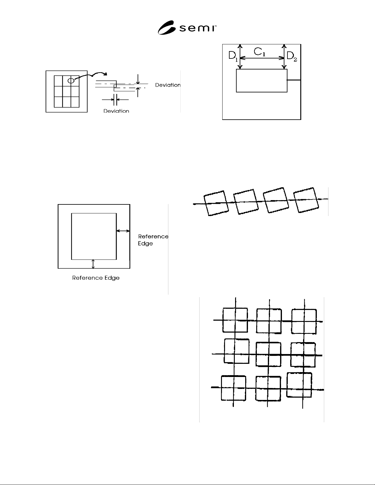
composition by a stepper). Usually, it is deviation as
shown in the following figure.
Figure 3
Stitching Error
5 Pattern Positioning Accur acy
5.1 Pattern Positioning Accuracy — Relation between
the actual and desired locations of a printed pattern on a
glass substrate.
5.2 End Plane Reference — Positioning accuracy of
the printed pattern measured from the reference edge of
a glass mask.
Figure 4
Pattern Positioning Accuracy
5.2.1 Reference Edge: Two adjacent edges are
considered as the reference edge.
5.3 Pattern Rotation — Deviation of a printed pattern
on a glass mask caused by rotation. Usually, it is
expressed by the difference between two measured
distances at separated points within one side as shown
in the figure.
θ = (D
1
- D
2
)/C
1
Usually fix the value of C
1
and use the value of D
1
- D
2
.
Figure 5
Pattern Rotation
5.4 Cell Rotation in Multiimages — Cell’s slant
rotation against axis of light in case of exposure by
stepper and similar equipment. (Generally, it is
measured by vernier outside of cells.)
Figure 6
Cell Rotation in Multiimages
5.5 Gaps of Cells in Multiimages — X and Y
directions’ gaps of cells against designed grating which
should be exposed primarily by stepper and similar
equipment. (Generally, it is measured by gaps between
cells which are next to each other with vernier outside
of cells.)
Figure 7
Gaps of Cells in Multiimages

SEMI D21-1000 © SEMI 1992, 20003
NOTICE: The user’s attention is called to the
possibility that compliance with this standard may
require use of copyrighted material or of an invention
covered by patent rights. By publication of this
standard, SEMI takes no position respecting the validity
of any patent rights or copyrights asserted in connection
with any item mentioned in this standard. Users of this
standard are expressly advised that determination of
any such patent rights or copyrights, and the risk of
infringement of such rights, are entirely their own
responsibility.
Copyright by SEMI® (Semiconductor Equipment and Materials
International), 3081 Zanker Road, San Jose, CA 95134. Reproduction o
f
the contents in whole or in part is forbidden without express written
consent of SEMI.
SEMI D22-1103 © SEMI 1999, 2003 1
SEMI D22-1103
TEST METHOD FOR THE DETERMINATION OF COLOR,
TRANSMITTANCE OF FPD COLOR FILTER ASSEMBLIES
This test method was technically approved by the Global Flat Panel Display Committee and is the direct
responsibility of the Japanese Flat Panel Display Committee. Current edition approved by the Japanese
Regional Standards Committee on August 8, 2003. Initially available at www.semi.org October 2003; to be
published November 2003. Originally published September 1999.
NOTICE: This document was completely rewritten in
2003.
1 Purpose
1.1 This standard establishes practices for measuring
selected characteristics of FPD color filters. These
methods are applicable to manufacturing, quality
control, and development operations.
2 Scope
2.1 This method is to be used by FPD color filter
suppliers and users to evaluate quality of products as
well as items under development.
2.2 This method shall be used in general to measure
the color characteristics and transmittance of FPD color
filter.
NOTICE: This standard does not purport to address
safety issues, if any, associated with its use. It is the
responsibility of the users of this standard to establish
appropriate safety and health practices and determine
the applicability of regulatory or other limitations prior
to use.
3 Referenced Standards
3.1 SEMI Standards
SEMI D13 — Terminology for FPD Color Filter
Assemblies
3.2 CIE Standards
1
CIE 1931 — Standard Colorimetric System
(Colorimetry – Official Recommendations of the CIE)
CIE 1976 (L*,a*,b*) — Color Space (Recommend-
ations on Uniform Color Spaces)
NOTICE: Unless otherwise indicated, all documents
cited shall be the latest published versions.
4 Summary of Method
4.1 Turn on the apparatus, and input measurement
parameters.
1 CIE International Commission on Illumination, Kegelgasse 27, A-
1030 Vienna, Austria
4.2 Warm up and stabilize the equipment.
4.3 Measure the reference quantity of light.
4.4 Set the sample on the measuring stage, and adjust
the point of measurement into the measuring spot.
4.5 Measure the sample quantity of light.
4.6 Print the results (color characteristics and
transmittance).
5 Apparatus
5.1 The measurement system shall have the following
specifications.
5.2 Wavelength range: variable between 380 and 780
mm, in increments of < 5nm.
5.3 Measuring area: Measuring spot size or the spot
size of incident beam on the sample surface is smaller
than the sub-pixel to be measured. (for example 2 to 50
micrometer in diameter).
5.4 Sample stage:
5.4.1 Sample surface can be set normal to the incident
beam. (See Figure 1)
5.4.2 The sample stage shall have a sufficient
mechanical travel to permit measurements within the
color filter area and in the transparent area of the
substrate outside the color filter material.
θ
Phot ometer
li
g
ht sour c
e
color filt er
Fi
g
ure 1