semi合集-English.pdf - 第442页
SEMI E63-1104 © SEMI 1997, 2004 3 and right of t he bilateral datum plane, an d centers of the top, mi ddle, and bottom pairs of threaded holes are to be located at z 78 above, z 75 below, an d z 73 below the horizontal …

SEMI E63-1104 © SEMI 1997, 2004 2
4.1.3 box a protective portable container for a
cassette and/or substrate(s).
4.1.4 box opener/loader the equipment component
that opens wafer carriers (if needed) and presents the
carriers to the equipment's wafer handler for unloading
and loading wafers.
4.1.5 carrier capacity the number of substrates that
a carrier holds (as defined in SEMI E1.9).
4.1.6 cassette an open structure that holds one or
more substrates.
4.1.7 equipment front end module (EFEM) consists
of the carrier handler that receives carriers from the
factory material handling system on one or more load
ports (as specified in SEMI E15.1), opens the carriers
(if needed), and may include a substrate handler for
unloading and loading wafers from the carrier to the
process part of the equipment.
4.1.8 facial datum plane a vertical plane that bisects
the wafers and that is parallel to the front side of the
carrier (where wafers are removed or inserted). On tool
load ports, it is also parallel to the load face plane
specified in SEMI E15 on the side of the tool where the
carrier is loaded and unloaded (as defined in SEMI
E57).
4.1.9 horizontal datum plane a horizontal plane
from which project the kinematic-coupling pins on
which the carrier sits. On tool load ports, it is at the load
height specified in SEMI E15 and might not be
physically realized as a surface (as defined in SEMI
E57).
4.1.10 load face plane the furthest physical vertical
boundary plane from the cassette centroid or carrier
centroid on the side (or sides) of the tool where loading
of the tool is intended (as defined in SEMI E15).
4.1.11 minienvironment a localized environment
created by an enclosure to isolate the product from
contamination and people.
4.1.12 pod a box having a Standard Mechanical
Interface (SMIF) per SEMI E19.
4.1.13 seal zone a surface on the tool at the BOLTS
plane for sealing to the box opener/loader.
4.1.14
wafer carrier any cassette, box, pod, or boat
that contains wafers (as defined in SEMI E15).
5 Requirements
5.1 Datum Planes The physical alignment
mechanism for the box consists of features (not
specified in this standard) on the box that mate with
three or six pins underneath as defined in SEMI E57.
Many of the dimensions of the BOLTS interface are
determined with respect to the three orthogonal datum
planes defined in that standard: the horizontal datum
plane, the facial datum plane, and the bilateral datum
plane. The BOLTS plane is defined to be parallel to and
at a distance y70 from the facial datum plane of the
carrier (when the carrier is docked and in position for
wafer extraction and insertion). If the carrier is rotated
after being placed on the loadport, the facial datum
plane of the carrier and the BOLTS plane may no
longer be parallel to the load face plane of the
equipment. If the carrier is not rotated, the distance
(called the docking stroke) between the facial datum
plane when the carrier is placed on the loadport
(undocked) and the facial datum plane when the carrier
is in position for wafer extraction and insertion
(docked) must be y76 (but this is only a requirement for
equipment delivered in the year 2000 or later). The
tolerance on y70 is the installation tolerance. The cycle-
to-cycle repeatability on y70 (without replacing the box
opener/loader unit) must be within y75.
5.2 Symmetry All of the dimensions for the interface
are bilaterally symmetric about the bilateral datum
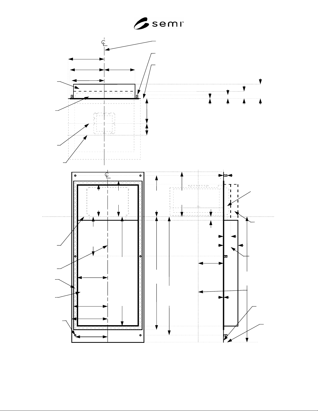
plane. These dimensions are shown in Figure 1 and
specified in Table 1.
5.3 Hole Opening The BOLTS interface consists of
a hole in the front of the tool at the BOLTS plane, a seal
zone surrounding the hole, six threaded holes for
bolting on the box opener/loader, reserved spaces for
the box opener/loader inside the tool from the hole, and
an exclusion volume for the box opener/loader outside
of the hole. The dimensions of the hole are defined by
x71, z71, and z76.
5.4 Seal Zone On the BOLTS plane surrounding the
hole opening must be a flat area for sealing between the
tool and the box opener/loader. The inner dimensions of
the seal zone are the same as the hole opening, and the
outer dimensions of the seal zone are defined by x72,
z72, and z77. The flatness of the seal zone must be
within y71, and the perpendicularity of the seal zone to
the facial and horizontal datum planes must be within
5.5
Bolt Holes At six points on the BOLTS plane
there must be threaded holes for bolting on the box
opener/loader. The opening of the threaded holes must
be within the flatness of the seal zone (y71), and the
holes must be at least y73 deep. The internal threads
must conform to the ISO/DIS 68-1 specification which
has a nominal diameter of 8 mm (0.31 in.), a thread
pitch of 1.25 mm (0.05 in.), a normal length of
engagement from 4 to 12 mm (0.16 to 0.47 in.), and no
allowance (variation from basic diameter). The centers
of the threaded holes are to be located at x73 to the left
SEMI E63-1104 © SEMI 1997, 2004 3
and right of the bilateral datum plane, and centers of the
top, middle, and bottom pairs of threaded holes are to
be located at z78 above, z75 below, and z73 below the
horizontal datum plane, respectively. Not all of these
bolt holes need to be used by every box opener/loader,
but all six threaded holes must be present on the tool.
Note that the middle pair of threaded holes is in the seal
zone, and so it may be covered up by some gaskets
(which are not specified here).
5.6 Reserved Spaces Inside the tool from the
BOLTS plane are volumes reserved for the box
opener/loader into which tool and its wafer handler may
not protrude. A permanent reserved space is bounded
by x70, y74, z70, and z80. When the door is closed,
there is an additional temporary reserved space
bounded by x70, y72, and z81. When the door is being
opened or closed by the box opener/loader, there is a
further temporary reserved space bounded by x70, y74,
and z81. When the door is fully open, it will be
withdrawn into the permanent reserved space, and the
tool wafer handler may extend into the box to extract or
insert wafers.
5.7 Exclusion Volume Outside the tool from the
BOLTS plane is a volume reserved for the box
opener/loader into which the exterior of the tool may
not protrude. This exclusion volume is bounded by x74,
z79, and the floor. Within these boundaries and outside
of the seal zone, no part of the tool may protrude closer
to the facial datum plane than the closest point of the
seal zone. Also, it is recommended that no part of the
tool should overhang the box opener/loader, even above
z79. Note that x74 has been chosen to allow the
minimum width between adjacent load ports defined in
SEMI E15.1.
5.8 Inner and Outer Radii All required concave
features may have a radius of up to r75 to allow
cleaning and to prevent contaminant build-up. All
required convex features may also have a radius of up
to r76 to prevent small contact patches with large
stresses that might cause wear and particles. Note that
these limits on the radius of all required features are
specified as a maximum (not a minimum) to ensure that
the required features are not rounded-off too much. The
lower bound on the radius is up to the tool supplier.
Note also that this radius applies to every required
feature unless another radius is called out specifically.
6 Related Documents
6.1
SEMI Standards
SEMI M31 Provisional Mechanical Specification for
Front-Opening Shipping Box Used to Transport and
Ship 300 mm Wafers
SEMI E84 Specification for Enhanced Carrier
Handoff Parallel I/O Interface
NOTICE: Unless otherwise indicated, all documents
cited shall be the latest published versions.
SEMI E63-1104 © SEMI 1997, 2004 4
permanent
reserved
space and
reserved
space when
door is
opening or
closing
reserved
space when
door is
closed
facial datum
plane:
when
carrier is
docked
when
carrier is
undocked
y
70 = 173±3
(install tolerance)
y
75 = ±0.5
(repeatability)
y
76 = 70+2/-0
(docking stroke
length required
by year 2000 if
the carrier is not
rotated)
y
71 = ±1
(flatness)
=0±0.1°
(perpendicularity to
facial and horizontal
datum planes)
y
72
57
y
74
100
y
73
40
x
73 =215±0.1
x
71 =208±1
(at seal zone)
x
70
207
(inside of tool)
x
72
236
x
74
237.5
bilateral datum plane
ISO M8-6H thread for bolt (6x)
BOLTS plane
Top View
Side View
reserved
space when
door is
closed
reserved
space when
door is
opening or
closing
permanent
reserved
space
facial datum
plane
BOLTS
plane
floor
z
77
423
z
76
=395±1
z
81
394
z
79
486
z
70
20
(900 mm, see
SEMI E15.1)
x
73=215±0.1
z
72
822
z
73
=832
±0.1
Front View
horizontal
datum
plane
bilateral
datum
plane
seal
zone
hole
ISO M8-6H
thread for
bolt (6x)
x
71=208±1
(at seal
zone)
x
70
207
(inside of
tool)
x
72
236
x
74
237.5
y
71 =±1
(flatness)
=0±0.1°
(perpen-
dicularity
to datum
planes)
y
72
57
y
74
100
z
71
=794±1
(at seal
zone)
z
80
793
(inside
of tool)
z
78
=455.5
±0.1
z
75
=150.25
±0.1
y
70
=173±3
(install
tolerance)
y
75=±0.5
(repeat-
ability)
y
73
40
Figure 1
Top, Front, and Side Views of Box Opener/Loader to Tool Standard (BOLTS) Interface