semi合集-English.pdf - 第1625页
SEMI E38-1296 © SEMI 1995 , 1996 14 Error exception con ditions may h ave associated recovery act ions which can be performed by the m odule resource to attempt to recover f r om the abnor mal situation. Alarm exception …
SEMI E38-1296 © SEMI 1995, 199613
The factory transfer resource may be an operator,
SMIF, AGV, or other mechanism. Its definition,
associated transfer jobs, and the handoff, are beyond the
scope of this standard. Factory material movement may
be achieved automatically using applicable SEMI
standards.
7.1.4.3 Carrier Mapping — The final element of
material movement in a cluster tool is the mapping of
single material in a carrier. Once a cassette is received
by the cluster tool, it is necessary to communicate the
presence and identifiers of the material it contains.
Batch process modules also require these carrier
mapping services in order to define loading of the
process carrier.
In carrier mapping, the carrier may be a cassette used to
hold single material loaded at the cassette module from
the factory, or a process carrier used to hold multiple
material for batch processing. For the purposes of
carrier mapping, these are equivalent, and the
relationships are shown in the material model, Figure 6.
A carrier has an ordered set of material slots, a
specialization of material location, each of which can
hold a single material. The material slot of a carrier is
only of interest when the carrier is in the cluster tool, so
it is viewed as a location of the module which contains
the carrier. In addition to occupancy, a single material
may be assigned to a material slot, indicating, for
example, the particular slot to which a single material
is to be moved when available. Information on material
presence and assignment of the material identifier may
be detected in the module or determined by the cluster
controller or a supervisory controller.
7.1.5 Exception Model — In an automated control
system where the operator interface is remote from the
module controller, it is necessary to have interactive
exception handling for error recovery. In addition to
exception reporting, a module requires input from a
decision authority to resolve recoverable abnormal
situations. These include exception conditions which
extend beyond the module domain and those for which
the module has insufficient information, such as in
hardware failure.
The decision authority in a cluster tool is the cluster
controller. It may interact with an operator to determine
the appropriate recovery action to perform.
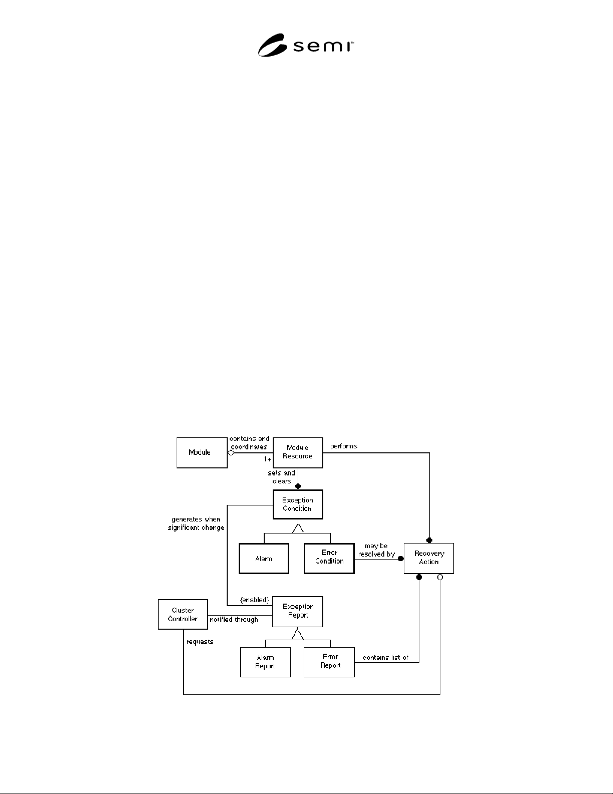
Figure 10 shows the exception model. Module
resources detect appropriate exception conditions,
which may be set or cleared. An abnormal situation is
indicated by the corresponding exception condition
being in the set state. A significant change in exception
condition information generates an exception report to
notify the decision authority. Both detection of the
abnormal situation and its resolution generate exception
reports. Reporting of each exception condition may be
enabled and disabled independently in order to mask
nuisance exceptions.
Figure 10
Exception Information Model
SEMI E38-1296 © SEMI 1995, 1996 14
Error exception conditions may have associated
recovery actions which can be performed by the module
resource to attempt to recover from the abnormal
situation. Alarm exception conditions cannot, by
definition, be resolved using recovery actions.
A list of possible recovery actions is included in a
posted error report. The decision authority can request
one of the offered recovery actions to resolve the error
condition. The selected recovery action is performed by
the appropriate module resource and may result in
clearing the error condition.
This model is used to establish the Exception
Management definition.
7.1.6 Recipe Management Model — Recipe
management in a module varies with the requirements
of the application. Simple modules do not provide local
recipe editing and don’t require management of
multiple logical domains (namespaces) and local recipe
version control.
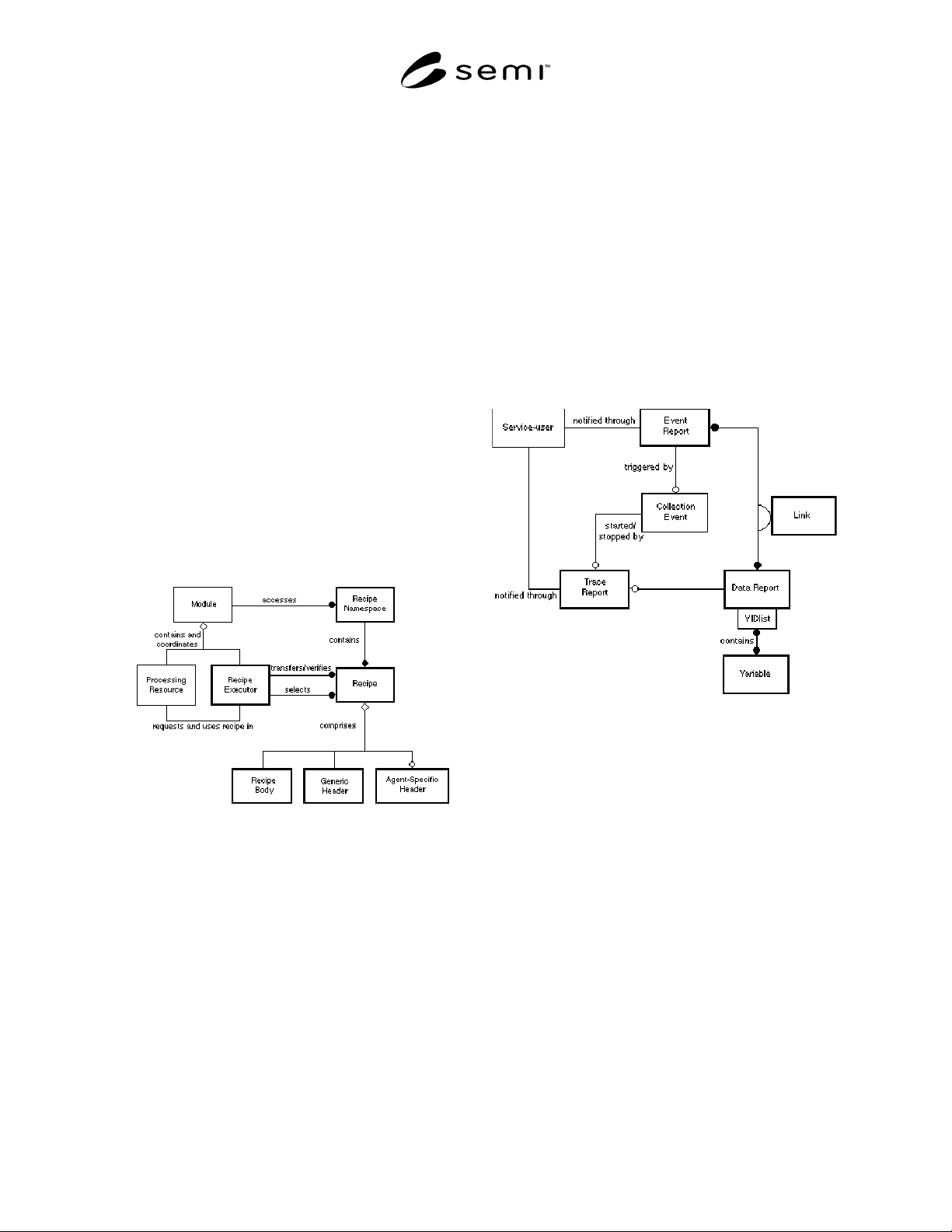
Figure 11 shows the full recipe management model for
a sophisticated module.
Figure 11
Recipe Management Information Model
Process recipes specify the actual parameters of the
processing to be achieved. The module processing
resource identifies, through the process job, the
required recipe(s) to be loaded by the recipe executor in
order to process a particular material.
The recipe executor accesses and selects recipes for
execution. It uploads and downloads recipes from the
cluster controller and is capable of verifying that a
recipe is syntactically correct. The recipe executor also
provides for a service-user to select a recipe to be
loaded into the recipe execution area. The recipe is
made up of a recipe body and may have headers if the
module supports recipe namespace management.
The module accesses recipe namespaces where
requested by service-users. A module which does not
provide local editing and linking of recipes does not
need recipe namespace management. Recipe namespace
management requires management of recipe generic
and agent (module) specific headers. For example, a
process module could manage a recipe namespace
containing its process and service recipes.
This model is used to establish the Recipe Management
services requirements for cluster tool modules.
7.1.7 Event Reporting Model
Figure 12
Event Reporting Information Model
Event reporting provides a dynamic and flexible means
by which a service-user can receive notification of
events and data relating to module resources.
The services-user can define and enable two types of
reporting, event reporting and trace reporting. Both may
convey data, the values of identified variables at the
data collection time. The variable identifiers required to
be reported are specified in the data report definition.
In event reporting, data reports are linked to event
report definitions associated with each collection event
type. On occurrence of the collection event, an event
report message is generated according to the event
report definition and the linked data report definitions.
Reporting may be enabled and disabled for each
collection event type. Data reports and links may be
predefined or specified dynamically by the service user.
Trace reporting is time-based data reporting. Trace
reporting is specified by the service-user dynamically
SEMI E38-1296 © SEMI 1995, 199615
as required. Collection events may initiate and
terminate the tracing in order to link reporting to
significant conditions, such as processing. The trace
data is collected at a frequency specified by the service-
user. Trace reports are generated according to the trace
report definition and the associated data report
definition.
Through associating the event report and trace report
definition with the service-user, the model provides for
the association of multiple service-users to a single
service-provider. This allows for event reporting
between modules where needed as well as the ability
for direct connection of a data acquisition entity
independent of the cluster controller.
7.2 Cluster Tool Module Message Flow — The
appropriate objects in the information models in the
previous section are grouped in the cluster tool module
types. The communications with the essential objects
are shown in the message flow diagrams in this section.
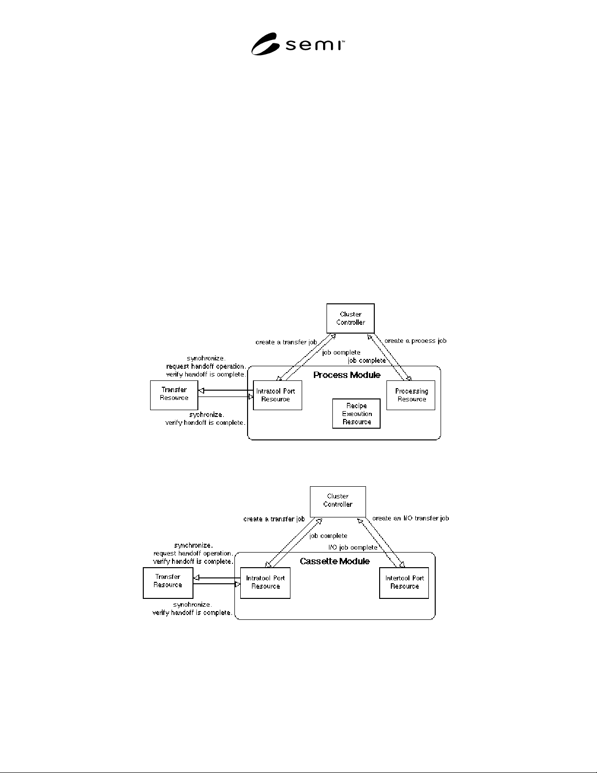
The diagrams show message flow between entities
within an agent (in this case a module) and those
outside the agent. Entities are rectangular boxes, and
the agent is a rounded box. As emphasis is on the
module and its services, only one agent is shown on
each diagram. Outside entities in the cluster tool
module communications domain appear within an agent
on another diagram. The messaging is shown by arrows
in each direction, with a brief label indicating the
services requested or provided.
The communications are shown for the primary control
of the process module (Figure 13), cassette module
(Figure 14), and transport module (Figure 15). Note that
the transport module transfer resource communicates
with multiple process and cassette module intratool port
resources.
Figure 13
Process Module Primary Control Message Flow
Figure 14
Cassette Module Primary Control Message Flow