semi合集-English.pdf - 第7200页
SEMI ME1392-0305 © SEMI 2003, 2005 9 9.5 Rel ated Information 3 pro vides a repo rting form at suggested for use. This format is general in nature and allows for vari ation of any sampl e or system pa rameters. 10 Precis…

SEMI ME1392-0305 © SEMI 2003, 2005 8
7 Procedure
7.1 Sample cleanliness can be a significant factor in the scatter level. The user should adopt a procedure for
cleaning samples prior to measurement and this cleaning procedure should be reported with the BRDF results.
7.2 Correct alignment of the source, sample, and receiver are essential for accurate BRDF measurements. A typical
example of a subtle error that can be introduced by misalignment occurs when the receiver does not rotate in
s
about the sample face. As
s
increases, the receiver field-of-view “walks off” the illuminated area, A, and the
measured BRDF is then lower than actual BRDF. Although it is not necessary to perform a total system alignment
every day, alignment must be verified on a daily basis for movable components.
7.3 After cleaning the sample and verification of alignment, the sample is inserted in the sample holder. The
detector voltage, V
d
, and the source monitor voltage, V
m
, are recorded for each parameter set of interest. For
example, BRDF measured in the plane-of-incidence requires changing
s
while holding other parameters constant.
The measurement results consist of three columns of data for
s
, V
d
, and V
m
. The constant parameters,
i
and
s
, are
retained in the header information for this data set. Post processing is used to calculate BRDF and express the
results in the desired tabular or graphical format, but P
s
can be calculated at this time. In this calculation, the ratio of
source monitor voltages is included to correct for variation of source intensity:
m
mid
s
V
VRV
P
(6)
where V
mi
= source monitor voltage (see ¶6.3.1).
7.4 BRDF can exhibit strong sensitivity to azimuthal orientation, spot size and position changes on the sample face.
Good operating practice dictates checking for sensitivity to these and other system parameters.
8 Calculation
8.1 The BRDF of an unknown sample is calculated at each incident and scattered direction from the following
relationship:
][sr
coscos
BRDF
1
si
d
m
mi
si
s
P
RV
V
V
P
P
(7)
The value of P
i
is determined by the normalization method used. The correct angular variables may also be
calculated in post processing with BRDF. In all cases
i
and
s
are referenced to the sample normal.
8.2 Many facilities prefer to store only raw data and calculate BRDF and display variables as required to produce a
graph or data table. If data are sent to another facility, it is essential to convert to BRDF and the angular variables
defined in this practice. A suggested reporting format is given in Related Information 3.
9 Report
9.1 BRDF data is expressed in tabular or graphical format as a function of the variable parameter. It is necessary to
state the accuracy of angular measurements and the size of the receiver solid angle, . These latter parameters are
important for small angle scatter. It is usually meaningless to measure within 1° of specular or to measure very
narrow “diffraction spikes” when spans several degrees.
9.2 It is necessary to furnish the instrument signature with the sample BRDF data so that the user can make an
informed decision about the angle where the sample’s scatter becomes lost in the signature. Correct comparison of
the signature with BRDF data requires multiplying the signature by the sample's specular reflectance for that portion
of the signature due to instrument scattered stray light (usually the case for
s
near specular). The portion of the
signature due to electronic noise is not reduced by the sample reflectance.
9.3 It is necessary to furnish the normalization method with BRDF data. If a relative normalization is used the
source of the reference sample BRDF must be stated.
9.4 BRDF data can span many decades so it is usually expressed in base ten exponential form or plotted on a
logarithmic scale.

SEMI ME1392-0305 © SEMI 2003, 2005 9
9.5 Related Information 3 provides a reporting format suggested for use. This format is general in nature and
allows for variation of any sample or system parameters.
10 Precision and Bias
10.1 Precision — The precision of the procedure outlined in this guide is inconclusive based on the results of an
interlaboratory round robin conducted in 1988.
8
This round robin was conducted at a single wavelength (632.8 m),
angle of incidence (10°), polarization state (s incident) and with four specific sample surfaces. It was found that
precision depends on the BRDF level and scatter angle.
9
Additional information on precision was accumulated in a
10.6 m round robin conducted in 1989.
10
10.1.1 A white diffuse sample with mean BRDF = 0.27/sr gave a fractional deviation (standard deviation of the 18
measurement sets divided by the mean BRDF) close to 17% at scatter angles from 15 to 70°. A black diffuse
sample with mean BRDF = 0.01/sr gave fractional deviations from 24 to 39% depending on scatter angle. Specular
mirrors gave fractional deviations from 31 to 134% depending on scatter angle. Variations were larger at large
scatter angles where detector noise levels of some instruments and errors in
s
had a large effect. These variations
are much larger then expected from a typical error analysis.
10.2 Bias — There is no bias inherent in this practice. BRDF is a number derived from the ratio of physical
parameters that can be specified in absolute units. However, individual laboratories may have measurement errors
that lead to systematic offsets, such as an inaccurately measured solid angle. Other possible mechanisms are
discussed in the literature.
9
It is not possible at this time to separate these systematic errors from bias; however,
intralaboratory measurements on the same instrument typically repeat within 5%.
7
11 Keywords
bidirectional reflectance distribution function (BRDF); diffuse; irradiance; power spectrum; radiance; reflectance;
reflectance factor; roughness; scatter; specular; total integrated scatter
8 Leonard, Thomas A. and Pantoliano, Michael, “BRDF Round Robin,” Proceedings SPIE 967, 226 (1988).
9 Leonard, Thomas A., “The Art of Optical Scatter Measurement,” Proceedings, Laser Induced Damage in Optical Materials: 1988 Symposium,
Special Publication 775 (National Institute of Standards and Technology, Gaithersburg, MD, 1988), pp. 42–47.
10 Leonard, Thomas A., Pantoliano, Michael, and Reilly, James, “Results of a CO
2
BRDF Round Robin,” Proceedings SPIE 1165, 444-449
(1989).
SEMI ME1392-0305 © SEMI 2003, 2005 10
APPENDIX 1
GEOMETRY
NOTICE: The material in this appendix is an official part of SEMI ME1392. It was developed during the original
approval of this standard by ASTM Committee E12 in 1996. SEMI approval was by full letter ballot procedures
with publication authorized by the NA Regional Standards Committee on December 10, 2004.
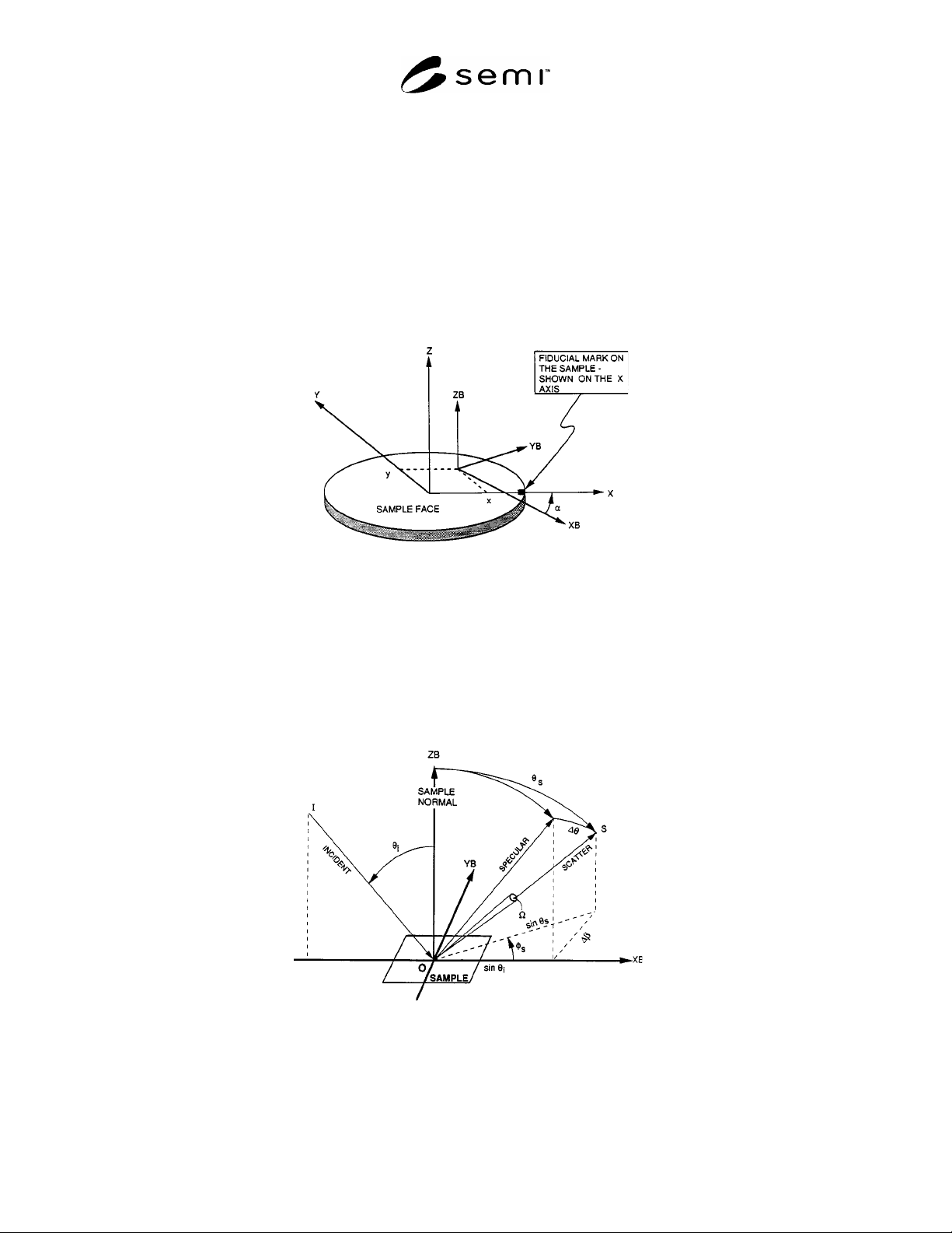
A1-1 Relationship between the Sample (X, Y, Z) and Beam (XB, YB, and ZB) Coordinate Systems
A1-1.1 The Z and ZB axes are always the local normal to the sample face. Locations on the sample face are
measured in the sample coordinate system. The incident and scatter directions are measured in the beam coordinate
system. If the sample fiducial mark is not an X axis mark, the intended value must be indicated on the sample (see
Figure A1-1).
NOTE 1: The X-Y zero position on the sample face is assumed to be the geometric center of the sample.
NOTE 2: The fiducial mark can be on the edge or back of the sample. For silicon wafers, the primary fiducial mark (flat or
notch) is on the circumference of the wafer at its intersection with the –y-axis.
Figure A1-1
Relationship Between Sample and Beam Coordinate Systems
A1-2 Angle Conventions for the Incident and Scattered Light in the Beam Coordinate System
A1-2.1 The projection of the incident direction onto the sample face is the XB axis. Azimuth angles are measured
from the XB axis. The incident azimuth angle,
i
, is always 180° so
s
can be used directly in the common form of
the grating equation (see Figure A1-2).
NOTE: The plane of incidence (PLIN) is the I-O-ZB plane. The scatter plane is the S-O-ZB plane.
Figure A1-2
Angle Conventions