semi合集-English.pdf - 第3971页
SEMI F42-0600 © SEMI 199 9, 2000 3 7.2.6 Proper con nections should be t r a ced and verified before energi zi ng. 7.3 Equi pment Safety 7.3.1 The sag gene rato r sho uld ha ve a f ail -sa fe desig n. NOTE 5: Su bjectin …
SEMI F42-0600 © SEMI 1999, 2000 2
5.1.5 sag generator — test apparatus capable of
reducing voltage supplied to the device under test for
specific time durations.
5.1.6 voltage sag — an rms reductio n in the ac
voltage, at power frequency, for durations from half-
cycle to a few seconds [IEEE 1250]. Also known as
voltage dip.
6 Test Apparatus
6.1 Data Acquisition System (DAS): The DAS will
allow monitoring of the device under test and selected
subsystems during the test. The DAS must measure the
voltage and current at least two cycles (40/33 ms)
before, during, and at least two cycles (40/33 ms) after
the voltage sag event. The DAS must have the
performance characteristics defined in Table 1.
NOTE 3: (40/33 ms) refers to 40 ms at 50 Hz or 33 ms at 60
Hz.
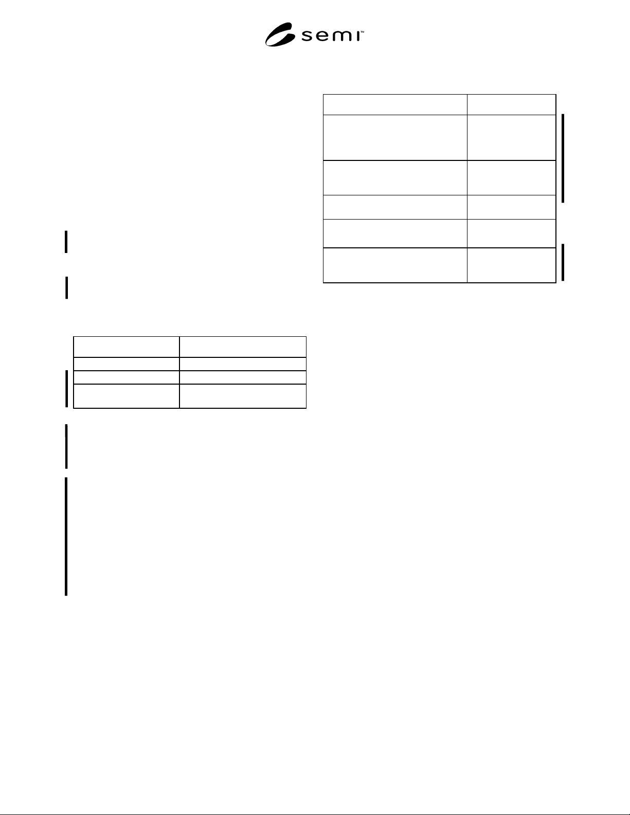
Table 1 Data Acquisition System Performance
Requirements
Parameter Requirement
Measurement Accuracy ± 3 percent of reading
Minimum Sample Rate 900 Hz
Minimum Number of
Analog Inputs
As required by the Test Plan
(see Section 10.1.4)
6.2 Digital Volt Meter (DVM) — A digital meter with
current and voltage measurement probes. Minimum
performance requirements of 1% accuracy, true rms,
and resolution of 3 1/2 digits.
6.3 Sag Generator — The sag generator must be
capable of providing voltage sags of controlled
magnitude and duration relative to the nominal supply
voltage of the DUT. The sag generator must be able to
create voltage sags over the range of durations and
magnitudes as required. The sag generator must be
capable of producing independent output voltages on
each phase of the load. The sag generator must have the
performance characteristics in Table 2 (see Related
Information 1).
Table 2 Sag Generator Performance Requirements
Parameter Requirement
Insertion loss (the difference
between sag generator input and
output voltages when set to 100%
of nominal)
Less than 1.5%
Change in output voltage as load is
varied from 0–100% (steady state
load regulation)
± 5%
Output current capability As required by the
DUT.
Capability to supply inrush current Not to be limited by
the sag generator.
Under all conditions, the
maximum deviation from required
voltage (dynamic load regulation)
Less than ± 10% for
not more than 1
cycle (20/17 ms).
7 Safety Precautions
NOTE 4: The following are safety guidelines for voltage sag
testing and as such should be considered only recommend-
ations since regional safety regulations vary. International,
national and local codes, regulations and laws should be
consulted to ensure that the equipment and procedures meet
regulatory requirements in each testing location.
7.1 Work should be conducted in accordance with
industry standard safety procedures. Since panels may
need to be open in order to connect voltage probes and
route power leads to and from the sag generator, this
work is classified as Type 2 Energized Electrical Work
per SEMI S2. Test equipment manufacturer’s safety
recommendations should be followed.
7.2 Worker Safety
7.2.1 During testing lock and tag (lockout/tagout)
procedures should be followed to control hazardous
energy (reference appropriate regional regulations and
requirements). No circuit should be connected or wired
when electricity is present. This includes power
connections as well as the connection of various
monitoring probes.
7.2.2 The area immediately surrounding the device
under test (DUT) should be cordoned off and appro-
priate signs like “Test In Progress” should be posted.
7.2.3 Appropriate personal protective equipment
should be worn at all times.
7.2.4 Only authorized personnel should be allowed
within the cordoned off test area.
7.2.5 Work should be done as described in the test
procedure (see Section 10).
SEMI F42-0600 © SEMI 1999, 20003
7.2.6 Proper connections should be traced and verified
before energizing.
7.3 Equipment Safety
7.3.1 The sag generator should have a fail-safe design.
NOTE 5: Subjecting equipment to repeated voltage sags of
less than 80% nominal for longer than 3 seconds may damage
equipment.
7.3.2 The sag generator should be protected by an
appropriately sized branch circuit breaker at the utility
power source. This will protect the sag generator and
DUT from short circuits and overcurrent conditions.
7.3.3 Every effort should be made to protect the DUT.
As with other equipment tests damage to the DUT is
possible. Although only a remote possibility, the
equipment owner should be made aware of the potential
for damage.
8 Sampling and Test Specim ens
8.1 Characterization tests are conducted on samples of
production articles, not on each item produced.
Characterization tests apply to equipment that is
manufactured to a single design either in multiple
quantities or one-of-a-kind. The equipment selected for
testing should reflect current production models of the
supplier.
8.2 The intent of this document is to make reasonable
efforts to test the semiconductor process, metrology,
and automated test equipment as a complete operating
system under the actual intended conditions of end use.
To simulate the worst-case condition, the tests
described in this document should be performed during
the most sensitive process mode of the equipment as
determined by the equipment supplier.
9 Test Setup
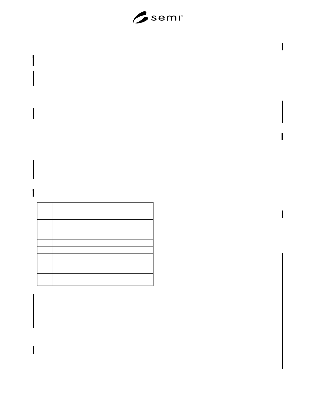
9.1 The test setup should consist of a sag generator
and a data acquisition system as shown in Figure 1.
9.2 When the current required by the DUT is within
the sag generator’s rating, the sag generator shall be
connected between the incoming utility power source
and the point of connection (POC) on the DUT. If the
current required by the DUT is greater than the rating of
the sag generator, then individual subsystems of the
DUT can be tested separately.
9.2.1 If DUT subsystem testing is required due to the
limitation of the sag generator, each subsystem must be
tested independently with the other parts of the DUT
operating. Tested in this manner, any interlocks or
alarms that might activate during the test will be
apparent. Testing the DUT main power module may
require providing power to only the main power
module, leaving the subsystems turned off. After the
characteristics of the DUT main power module EMO
circuit are known, testing of DUT subsystems can begin
as described.
9.2.2 Power down the DUT.
Sag
Generator
Device
Under Test
(DUT)
Data
Acquisition
System
(DAS)
N
ominal
Voltage
Test
Voltage
Equipment and
Sub-component
Measurements
POC
Utility Power
Source Branch
Circuit Breaker
NOTE: Single-phase test fixture is shown for clarity.
Figure 1
Test Setup
SEMI F42-0600 © SEMI 1999, 2000 4
9.2.3 De-energize and lockout/tagout the DUT POC.
9.2.4 De-energize and lockout/tagout the voltage
supply at the DUT utility power source branch circuit
breaker.
9.2.5 Identify the utility power source branch circuit
breaker to be used to power the sag generator, then, turn
off and lockout/tagout this device.
9.2.6 Following the sag generator manufacturer’s
instructions, connect the input of the sag generator for
each phase, ground, and neutral (if required) to the
utility power source branch circuit breaker identified in
Section 9.2.5.
9.2.7 Following the sag generator manufacturer’s
instructions, connect the output of the sag generator to
the DUT POC.
9.2.8 Following the DAS manufacturer’s instructions,
connect the DAS channels to the appropriate
measurement points on the DUT. The data acquisition
measurement points should be defined in the test plan
(see Section 10.1.4). Typical data acquisition measure-
ment points for semiconductor equipment are listed in
Table 3.
Table 3 Typical Data Acquisition Measurement
Points
No Data Acquisition Measurement Points
1 Ia, phase A current
2 Ib, phase B current
3 Ic, phase C current
4 Va-n, phase a-n voltage
5 Vb-n, phase b-n voltage
6 Vc-n, phase c-n voltage
7 Instrument Power Supplies output voltage
8 Emergency Off Relay contact
9 Equipment power contactor contact
10 Equipment controller power supplies output
voltage
9.2.9 During all voltage sag tests, the output of the sag
generator must be monitored by the DAS system. The
magnitude of the DAS monitored sag waveform must
be used to determine the magnitude of the actual event
since the magnitude may vary from the pre-sag setting
on the test equipment.
9.2.10 Visually inspect all connections.
9.2.11 Remove the lockout/tagout at the sag generator
utility power supply branch circuit breaker.
9.2.12 Energize the sag generator’s utility power
source branch circuit.
9.2.13 Initialize the sag generator system and set the
output for 100% of the DUT nameplate nominal
voltage.
9.2.14 Using a digital voltmeter, measure and record
the phase voltage(s) at the output of the sag generator.
9.2.15 Remove lockout/tagout at the DUT POC.
9.2.16 Energize the DUT.
9.2.17 Bring the DUT on-line in an idle state.
9.2.18 Using a digital voltmeter, measure and record
the phase voltage(s) at the output of the sag generator.
If needed, adjust the output of the sag generator for
100% of the DUT nameplate nominal voltage.
9.2.19 Set the sag generator for a 95% of DUT
nominal, 10 cycle (200/167 ms) sag voltage on one
phase.
9.2.20 From the sag generator controller, trigger the
sag event.
9.2.21 From the DAS, verify that the test sag event is
within the specified tolerance.
9.2.22 From the DAS, verify that all monitoring points
are recording the expected status information.
10 Test Procedure
10.1 In order to arrive at meaningful and comparable
results from voltage sag immunity testing on
semiconductor equipment the following steps should be
followed.
10.1.1 The test engineer should first study and
understand the DUT power flow and safety interlocking
systems of the DUT.
10.1.2 The test engineer should then determine the
purpose of the test (e.g. To characterize the
susceptibility of the DUT to voltage sags within a
defined duration range and to a defined minimum
voltage magnitude).
10.1.2.1 The test engineer should define the duration
range minimum and maximum over which the test
voltage sag should be applied to the DUT (e.g. 0.05
seconds to 1.0 seconds, as described in voltage sag ride-
through specification, etc.).
10.1.2.2 The test engineer should define the voltage
magnitude minimum(s) that should be applied to the
DUT over the test duration range (e.g. 0 volts nominal
for maximum duration, as described in voltage sag ride-
through specification, etc.).
10.1.3 The test engineer should define that testing is
complete for each phase mode when either an
equipment interrupt occurs at the minimum test