semi合集-English.pdf - 第4283页
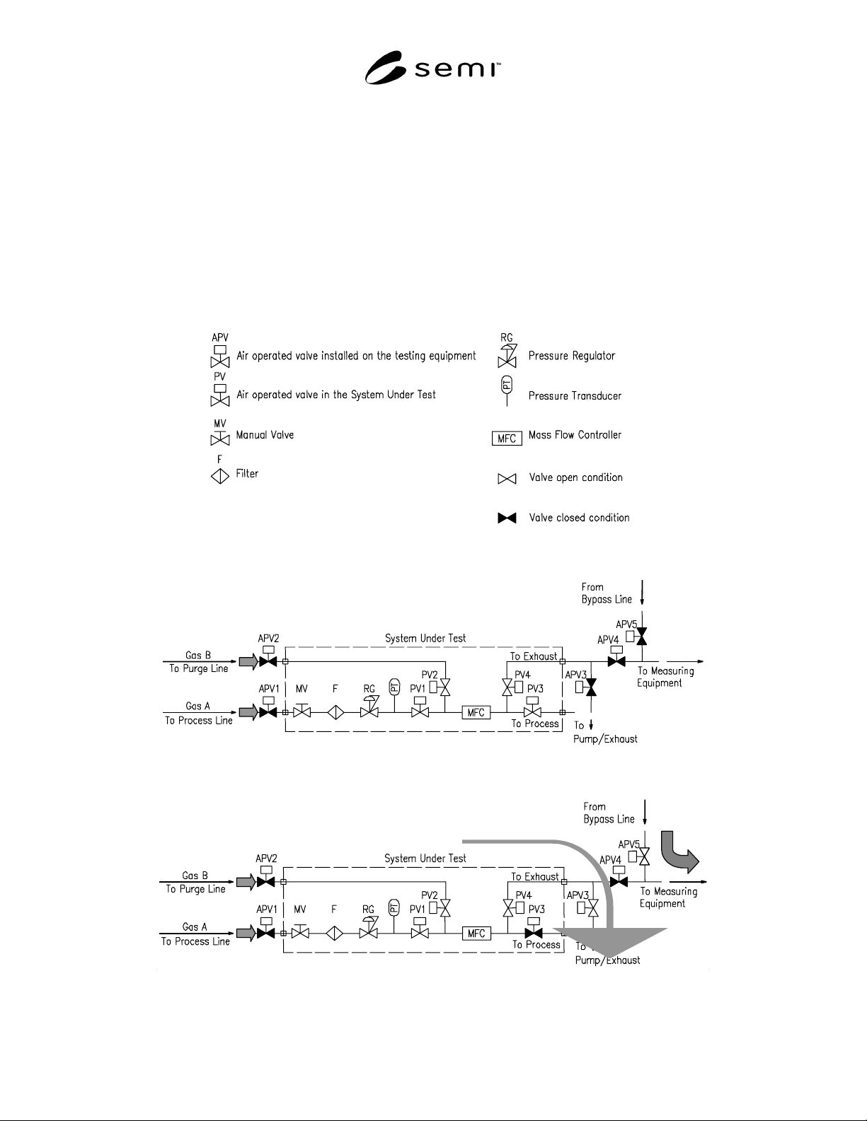
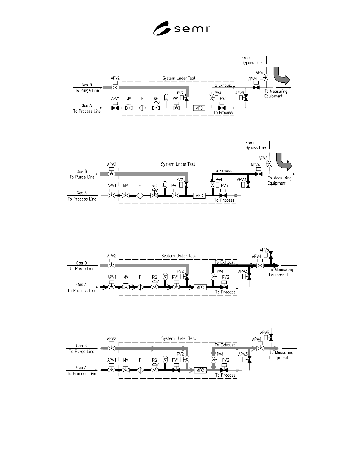
SEMI F80-1103 © SEMI 2003 3 (3) Figure 4 Procedure 7.1.5 (4) Figure 5 Procedure 7.1.6 Figure 6 Procedure 7.1.7 Figure 7 Procedure 7.1.8
SEMI F80-1103 © SEMI 2003 2
7.1.5 Open APV2 and flow Gas B from the Purge line. When flowing, close APV3 and fill the line with Gas B up
to PV2. Then, close PV2. Gas B also fills the line downstream of PV2. Open APV3, vacuum inside of the line, and
vent Gas B. Then, close APV3. (3) (See Figure 4.)
7.1.6 (a) Open APV1 and flow Gas A from the Process line. (b) Close PV1, open APV3 and vacuum the process
line. Then, Close APV3, open and close PV1, and open APV3. (c) Repeat this operation (b) 3 times and close APV3
to sufficiently fill process line with Gas A. (4) (See Figure 5.)
7.1.7 Close APV5. Then open APV4 and flow Gas A to the System Under Test. Measure the concentration of Gas
A by measuring equipment. (See Figure 6.)
7.1.8 Close PV1, open PV2 and flow Gas B to the System Under Test. The measuring equipment continuously
monitors the Gas A concentration. Record the time to achieve required concentration for Gas A from the start of
flowing Gas B. (See Figure 7.)
Figure 1
Abbreviations and Symbols
Figure 2
Gas Change/Purge Efficiency Test Schematic Case 1
(1)
(2)
Figure 3
Procedure 7.1.4
SEMI F80-1103 © SEMI 2003 3
(3)
Figure 4
Procedure 7.1.5
(4)
Figure 5
Procedure 7.1.6
Figure 6
Procedure 7.1.7
Figure 7
Procedure 7.1.8
SEMI F80-1103 © SEMI 2003 4
7.2 Case (2) — This is the test method in consideration
of gas change in the gas delivery system.
7.2.1 A recommended test flow schematic is shown in
Figure 8.
7.2.2 The test is to evaluate a gas change performance
in the gas delivery systems by using process line.
7.2.3 Set each component for the following condition
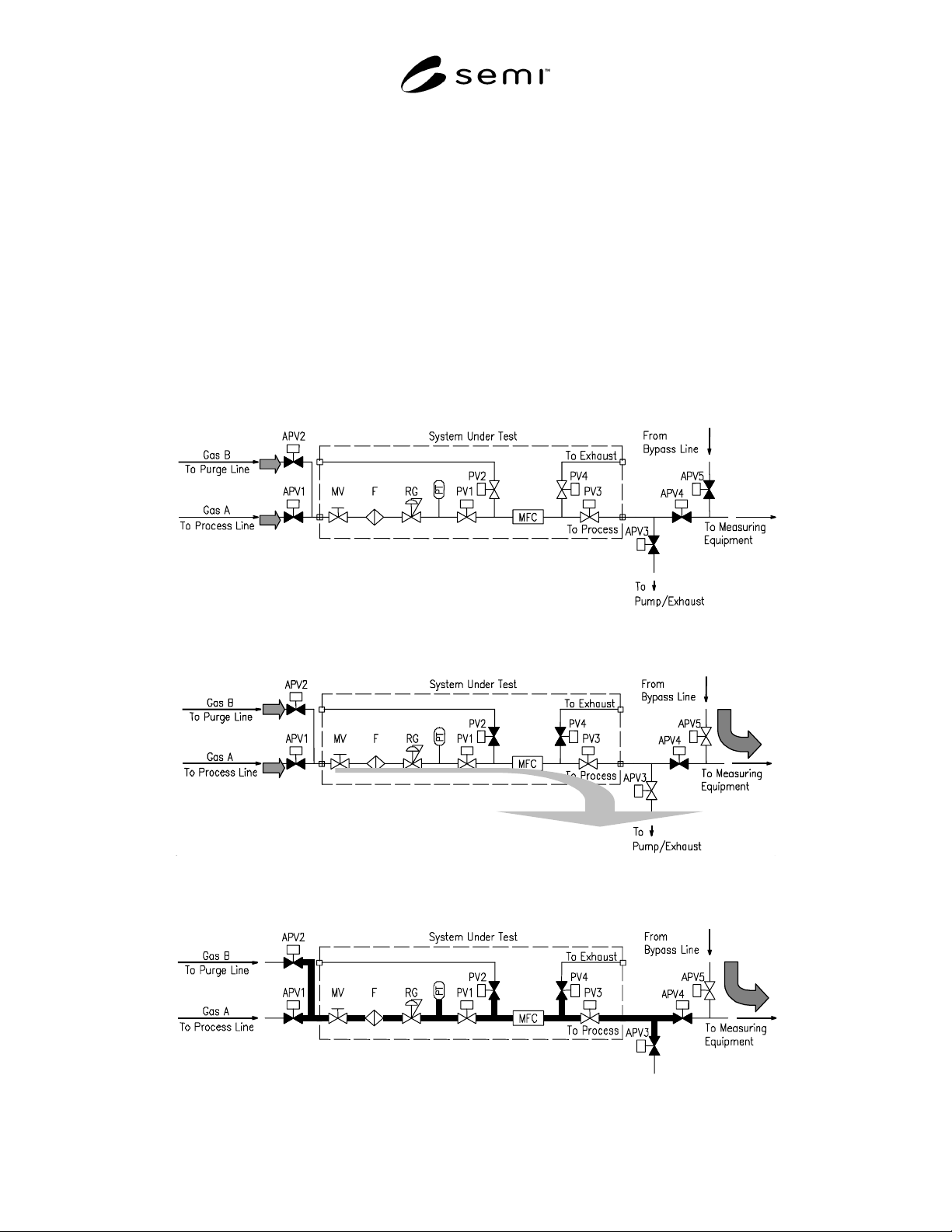
before starting the test. APV1, APV2, APV3, APV4,
and APV5 are closed condition. Rest of the components
in the System Under Test are open condition. Supply
Gas A to the upstream of APV1. Supply Gas B to the
upstream of APV2. (See Figure 8.)
7.2.4 Open APV5 and flow Gas A from Bypass line.
(1) Close PV2 and PV4, open APV3, and vacuum the
System Under Test. (2) (See Figure 9.)
7.2.5 (a) Close APV3, open APV1, and flow Gas A to
process line. (b) Close APV1, open APV3, and vacuum
process line. Then, close APV3, open and close APV1,
and open APV3. (c) Repeat this operation (b) 3 times
and close APV3 to sufficiently fill process line with
Gas A. (3) (See Figure 10.)
7.2.6 Open APV1and close APV5. Then open APV4
and flow Gas A to the System Under Test. Measure the
concentration of Gas A by measuring equipment. (See
Figure 11.)
7.2.7 Close APV1, open APV2, and flow Gas B to the
System Under Test. The measuring equipment
continuously monitors the Gas A concentration. Record
the time to achieve required concentration for Gas A
from the start of flowing Gas B. (See Figure 12.)
Figure 8
Gas Change/Purge Efficiency Test Schematic Case 2
(1)
(2)
Figure 9
Procedure 7.2.4
(3)
Figure 10
Procedure 7.2.5