semi合集-English.pdf - 第3742页
SEMI F1-96 © SEMI 19 90, 1996 5 8.4 C omponents 8.4.1 Inbo ard 8.4.1.1 Ref erence Method — ASTM E 4 9 8, Method A. Component acceptance shall be based upon total compon e nt integrity in accordan ce with ASTM E 498, Arti…
SEMI F1-96 © SEMI 1990, 1996 4
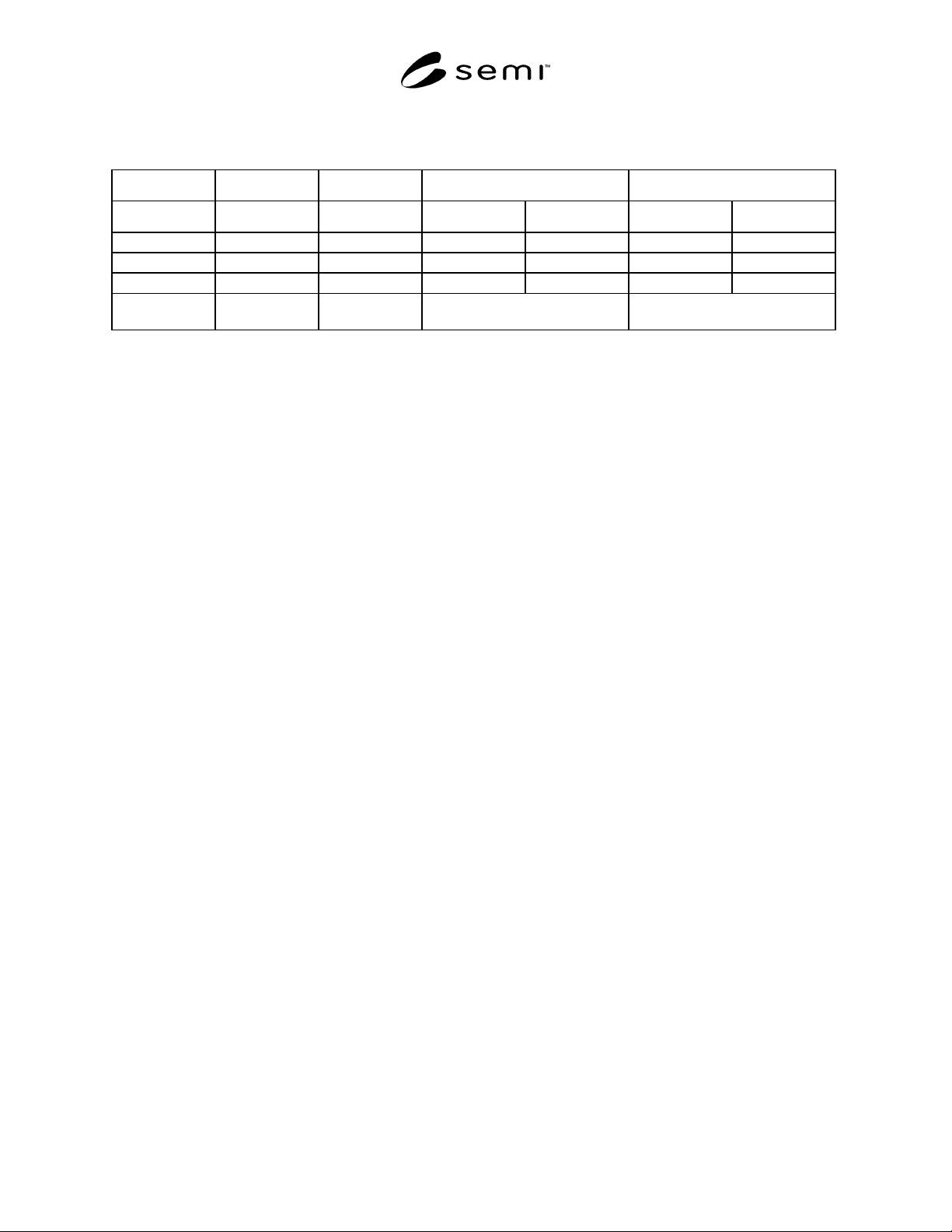
7.4 Leak Rate Limits
Table 1
Direction Component Component Subsystem System
kPa - L/sec atm - cc/sec kPa - L/sec atm - cc/sec kPa - L/sec atm - cc/sec
Inboard 10
-10
10
-9
10
-9
10
-8
10
-10
(per point) 10
-9
Internal 10
-10
10
-9
10
-10
10
-9
10
-10
10
-9
Outboard 10
-10
10
-9
10
-9
10
-8
1 ppm
(or 1 ppm increase in atmospheric
concentration if by probe method)
1 ppm increase in atmospheric
concentration
NOTES:
a. The internal leakage specifications apply only if the test object is rated for positive closure.
b. The internal leakage specification applies to each positive closure. If positive shutoff devices are in parallel, the specification applies
to the parallel devices as a group.
c. When piping systems or components employ polymeric seals, the internal and outboard leak rates specified above shall be modified by
multiplying the stated values by 100.
d. When new construction projects preclude measurement of outboard leakage at the leak rates specified above, the outboard leakage
limits shall be modified by multiplying the stated values by 100.
8 Test Methods
8.1 Dangers
8.1.1 Testing of systems, subsystems, or components with high pressure gas could cause explosive rupture of these
items, with the resulting fragmentation causing death or serious injury. In addition, if a component of the system
under test were to fail, an unrestricted supply of tracer gas could cause pressurization and rupture of the test
enclosure. Such testing shall not be performed without shielding that will protect the operator and other personnel in
the event of equipment failure. The source of tracer gas should be provided with a suitable device that will limit or
shut off the flow in the event of component rupture.
8.1.2 Some elements of a piping system may not be designed for pressurization. Pressurization of such system
elements could cause explosive rupture, with the resulting fragmentation causing death or serious injury. Such
elements shall not be tested in a manner inconsistent with the manufacturer’s specifications. Valves used to isolate
these elements of systems must be rated for higher pressure than the proposed test pressure.
8.1.3 Some components may be designed for closure only in one direction or only under pressure or vacuum.
Testing of such components in a manner other than that for which they are designed could cause explosive rupture,
with the resulting fragmentation causing death or serious injury. Such components shall not be tested in a manner
inconsistent with the manufacturer’s specifications.
8.2 Tracer Gas — (Unless otherwise specified in Sections 8.4 through 8.6.)
8.2.1 For those tests in which the test object is enclosed in or sprayed with tracer gas, 100% helium.
8.2.2 For those tests in which the test object is pressurized with tracer gas, 101.3 kPa (1 atm) of helium plus
nitrogen to pressurize to the design pressure.
8.2.3 The use of helium with a purity level of less than 100 ppb total contaminants and filtered at point of use to
less than 0.1 µm is required.
8.2.4 Inboard tests are performed at one atmosphere.
8.2.5 Internal and outboard tests are performed at the design pressure.
8.3 The use of a dry, oil-free helium mass spectrometer leak detector is recommended to prevent hydrocarbon
contamination of the piping system or component during inboard and internal leak testing.

SEMI F1-96 © SEMI 1990, 19965
8.4 Components
8.4.1 Inboard
8.4.1.1 Reference Method — ASTM E 498, Method A.
Component acceptance shall be based upon total
component integrity in accordance with ASTM E 498,
Article 6.8. Components that are too large to enclose in
a single helium envelope may be enclosed in segments
to determine total integrity.
8.4.1.2 Test each component for total inboard leakage
by introducing helium into a bag or other enclosure
around the component. Ensure that the enclosure is
sufficiently well-purged of air to minimize dilution of
the helium. In instances where the bagging technique is
not practical, the inboard leakage method of Section
8.6.1.2 may be substituted.
8.4.1.3 Test Time — Monitor the leak rate for 15
seconds.
8.4.2 Internal–Qualification Test
8.4.2.1 Reference Method — ASTM E 498, Method A.
Connect the outlet side of the closed component to the
leak detector. Apply tracer gas at the component’s
design pressure to the inlet side. Inlet and outlet sides
shall be as designated by the manufacturer.
8.4.2.2 Tracer Gas — 100% helium.
8.4.2.3 Test Time — Monitor the leak rate for 15
seconds.
8.4.3 Internal–Acceptance Test
8.4.3.1 Reference Method — ASTM E 498, Method A.
Connect the outlet side of the closed component to leak
detector. Apply tracer gas at atmospheric pressure to
the inlet side. Inlet and outlet sides shall be as
designated by the manufacturer.
8.4.3.2 Tracer Gas — 100% helium.
8.4.3.3 Tracer Gas Pressure — Atmospheric.
8.4.3.4 Test Tim — Monitor the leak rate for 15
seconds.
8.4.4 Outboard―Method 1
8.4.4.1 Reference Method — ASTM E 498, Method B,
modified as follows:
a. Cap the outlet of the component with a high
integrity fitting.
b. For valves and regulators, open the flow path
through the component. Install the component in a
vacuum chamber. A leak tight gas flow passage
must extend from the test component to the exterior
of the vacuum chamber.
c. Connect the leak detector to the vacuum chamber
and evacuate the chamber.
d. Pressurize the test component.
NOTE: Special fixtures may be required to test components
with tube stub ends to insure personnel safety and to prevent
component damage.
8.4.4.2 Test Time — Maintain the test condition for
one minute.
8.4.5 Outboard–Method 2 — Same as for Method 1,
except use 100% helium as the tracer gas.
8.4.6 Unassembled Components
8.4.6.1 Components that are assembled by the
purchaser, rather than the manufacturer, or that are
altered or repaired by the purchaser, shall be tested by
the purchaser in accordance with this specification.
8.4.6.2 Test of such components by the purchaser shall
not be performed under conditions that exceed the
manufacturer’s ratings.
8.5 Subsystems
8.5.1 Inboard
8.5.1.1 Reference Method — ASTM E 498, Method A.
Subsystem acceptance shall be based upon total
subsystem integrity in accordance with ASTM E 498,
Article 6.8.
8.5.1.2 Test for total inboard leakage by introducing
helium into a bag or other enclosure around the
subsystem. Ensure that the enclosure is sufficiently
well-purged of air to minimize dilution of the helium.
In instances where the bagging technique is not
practical, the inboard leakage method of Section 8.6.1.2
may be substituted.
8.5.1.3 Test time should be based on actual times to
record a standard capillary leak placed at the furthest
point in the subsystem from the leak detector.
8.5.1.4 Subsystems that are too large to enclose in a
single helium envelope may be tested in segments to
determine total integrity.
8.5.2 Internal―Method 1
8.5.2.1 Reference Method — ASTM E 498, Method A,
modified as follows:
a. Close the shutoff valve and pressurize the inlet with
tracer gas.
b. Connect the leak detector to the closest point
available to the valve outlet. Keep the evacuated
portion of the subsystem as small as practicable.

SEMI F1-96 © SEMI 1990, 1996 6
8.5.2.2 Test each subsystem for internal leakage of
each shutoff valve.
8.5.2.3 Test time should be based on actual times to
record a standard capillary leak placed at the furthest
point in the subsystem from the leak detector.
8.5.3 Internal―Method 2 — As in Method 1, except
use 100% helium as the tracer gas.
8.5.4 Outboard――Method 1
8.5.4.1 Reference Method — ASTM E 493, Method B,
modified such that the subsystem shall be prefilled and
maintained at constant pressure during the test.
NOTE: The pressure may be different for different portions of
the subsystem.
8.5.4.2 Test Time — Monitor the leak rate for 15
seconds.
8.5.5 Outboard――Method 2
8.5.5.1 Reference Method — ASTM E 499, Method A,
direct probing. Examine each joint with a detector
probe.
8.6 Systems
8.6.1 Inboard
8.6.1.1 Reference Method — ASTM E 498, Method A.
8.6.1.2 Test each system for total inboard leakage by
spraying a small stream of tracer gas around each point
of possible leakage.
8.6.1.3 Test time should be based on actual times to
record a standard capillary leak placed at the furthest
point in the system from the leak detector.
8.6.2 Internal
8.6.2.1 Reference Method — ASTM E 498, Method A,
modified as follows:
a. Close the shutoff valve and pressurize the inlet with
tracer gas.
b. Connect the leak detector to the closest point
available to the valve outlet. Keep the evacuated
portion of the subsystem as small as practicable.
8.6.2.2 Test each subsystem for internal leakage of
each shutoff valve.
8.6.2.3 Test time should be based on actual time to
record a standard capillary leak placed at the furthest
point in the subsystem from the leak detector.
8.6.3 Internal―Method 2 — Same as in Method 1,
except use 100% helium as the tracer gas.
8.6.4 Outboard
8.6.4.1 Reference Method — ASTM E 499, Method A,
Direct Probing. Each joint shall be examined with a
detector probe.
9 Certification
When specified in the purchase order or contract, the
manufacturer’s or supplier’s certification shall be
furnished to the purchaser stating that the articles
furnished have been tested in accordance with
applicable paragraphs of this specification and the
requirements have been met. When specified in the
purchase order or contract, a report of the test results
shall be furnished.
10 Related Documents
10.1 ANSI Standard
2
ANSI/ASME B31.3 — Chemical Plant and Petroleum
Refinery Piping
10.2 ASTM Standards
3
ASTM E 425 — Standard Definitions of Terms Relating
to Leak Testing
ASTM E 479 — Standard Guide for Preparation of a
Leak Testing Specification
10.3 Other Document
4
McMaster, Robert C., ed., Nondestructive Testing
Handbook, 2nd ed., Volume One: Leak Testing.
2 American National Standards Institute, 1430 Broadway, New York,
NY 10018
3 American Society for Testing and Materials, 100 Barr Harbor
Drive, West Conshohoken, PA 19428-2959
4 American Society for Nondestructive Testing, 4153 Arlingate
Plaza, Caller Number 28518, Columbus, OH 43228