semi合集-English.pdf - 第741页
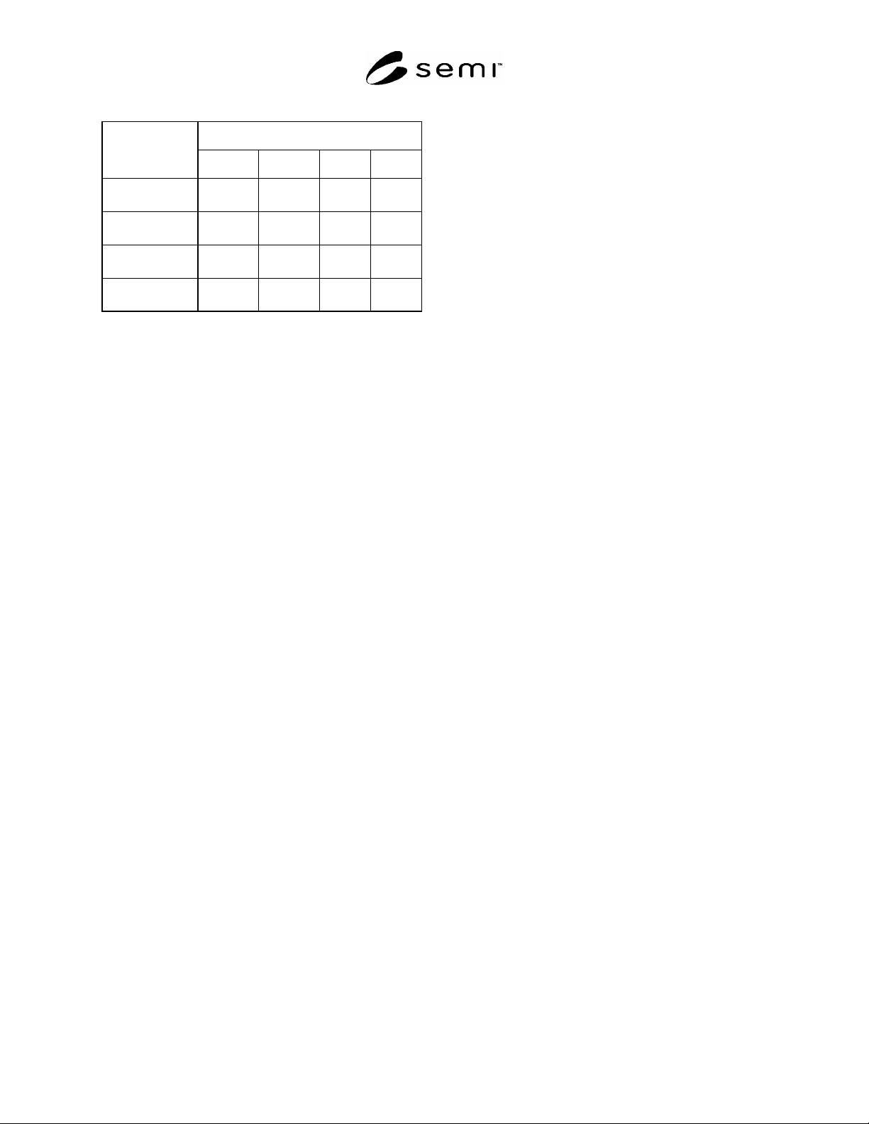
SEMI E100-1104 © SEMI 2000, 2003 4 Table 1 Info Pad Assignmen ts Info Pad RSP Configuration A B C D 230 mm reticle not defined not defined up down 6 inch reticle not defined not defined down down to be assigned not defin…

SEMI E100-1104 © SEMI 2000, 2004 3
bisecting plane through the reticle, parallel to the facial
reference plane must be within y133 of the facial
reference plane of the load port when the reticle is
seated in the carrier. When the carrier is open, it must
provide a horizontal reticle capture range of x135 and
y135. This capture range must be provided at z162
above the horizontal reference plane.
6.4 Exclusion Volumes — The interior of the RSP must
never intrude into the pellicle exclusion volumes, and
must not intrude into the end-effector exclusion
volumes or safety rail exclusion volumes when the
carrier is open. Where the exclusion volumes overlap,
the end-effector exclusion volume is reduced by the
pellicle exclusion volume when handling pelliclized or
chrome-down reticles.
6.4.1 End-Effector Exclusion Volumes — Volumes in
an opened pod which must be free for the end-effector
to enter and handle the reticle as defined by x116, x132,
y136, x144, x146, y144, z159, and z160 for a 230 mm
RSP, and by x118, x143, x145, y143, z159, and z160 for
a 6 inch RSP. No obstructions should exist in the end-
effector exclusion volume which extends in the
direction normal to the facial reference plane.
6.4.2 Pellicle Exclusion Volumes — Volumes in the
pod below the reticle which must remain free from
intrusion to accommodate the pellicle mounted on the
reticle. No obstructions should exist in the pellicle
exclusion volume which extends in the direction normal
to the facial reference plane as defined by x115, z159
and z161 for a 230 mm RSP, and by x119, z159 and
z161 for a 6 inch RSP. No obstructions should exist in
the transverse pellicle exclusion volume which extends
in the direction normal to the bilateral reference plane
as defined by y129, z159 and z163 for a 230 mm RSP,
and by y130, z
159 and z163 for a 6 inch RSP.
NOTE 1: The transverse pellicle exclusion volume is only
intended to specify where the reticle supports in the pod
cannot exist. Reticles with the pellicles transverse are
typically handled with end-effectors which grip from above
the reticle.
6.4.3 Safety Rail Exclusion Volumes — Volumes in an
opened pod which must remain free from intrusion to
accommodate safety rails which may be used on end-
effectors to protect the edge of the reticle during
handling. No obstructions should exist in the safety
rail exclusion volumes which extend in the direction
normal to the facial reference plane as defined by x137
and z167 for a 230 mm, and by x138 and z167 for a 6
inch RSP.
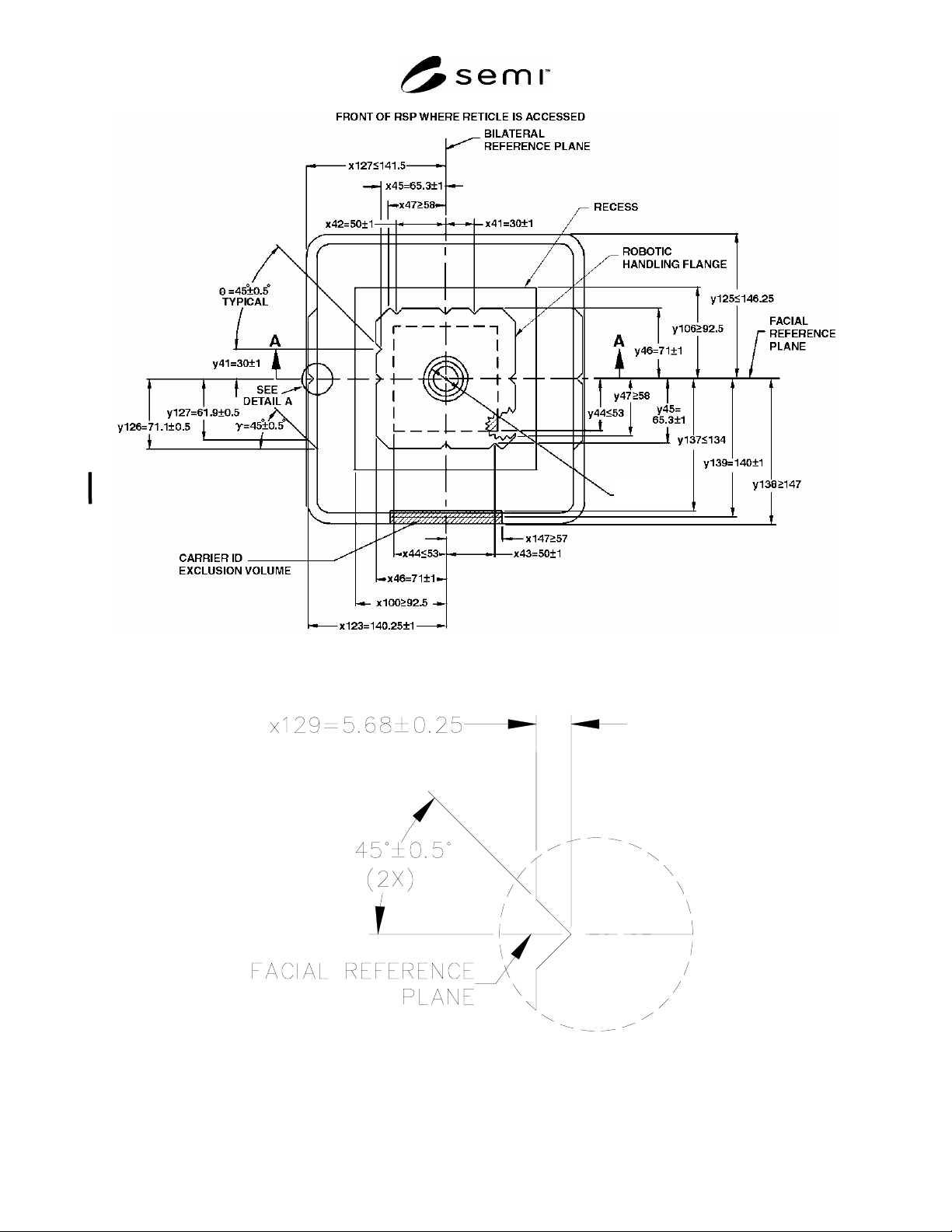
6.5 External Dimensions — Figures 1, 2 and 3 show,
respectively, the external top view, a detail and the
front view of the RSP. Table 2 defines all of the
external dimensions of the RSP (equivalent for both the
6 inch and the 230 mm versions).
6.6 Internal Dimensions — Figures 4 through 8 show
internal dimensions for the 6 inch and 230 mm versions
of the RSP. Table 2 defines all internal dimensions
which are common to the 6 inch and 230 mm RSP.
Table 3 defines the internal dimensions which apply
only to the 230 mm RSP. Table 4 defines the internal
dimensions which apply only to the 6 inch RSP. The
maximum height of the features which support the
reticle are given by z164 for a 230 mm RSP and z165
for a 6 inch RSP.
NOTE 2: The maximum height of the reticle supports, plus
the clearance between the reticle supports and reticle (chosen
by the tool supplier) determine the height the reticle must be
lifted before being extracted from, or inserted into the RSP.
6.7 Robotic Handling Flange — On the top of the pod
is an optional handling flange for automated
manipulation of the RSP. Figures 1, 3, and 5 show
dimensions for the robotic handling flange. Table 2
defines the dimensions for the robotic handling flange.
6.8 Side Handling Flanges — On the sides of the pod
parallel to the bilateral reference plane are optional
handling flanges for automated manipulation of the
RSP. Figures 1, 2, and 3 show dimensions for the side
handling flanges. Table 2 defines the dimensions for the
side handling flanges. No obstructions may exist in the
side handling exclusion volumes which extend in the
direction normal to the facial reference plane as defined
by x136 and z166 when the side handling flanges are
present.
6.9 Kinematic Coupling — The RSP door must have
the capability of registering on the kinematic pins
defined in SEMI E57. The features that mate with the
pins must provide a lead-in capability that corrects an
RSP misalignment no greater than r19 in any horizontal
direction. However, it is recommended that robots
placing RSPs on kinematic couplings use as little of this
lead-in capability as possible to avoid wear.
6.10 Carrier Sensing Pads — The RSP door must have
carrier sensing pads as defined in SEMI E1.9.
6.11 Info Pads — When the RSP is placed on a port,
the info pads A, B, C, and D communicate information
about the RSP configuration. Figures 6 and 8 show the
dimensions of the info pads. Table 2 defines the info
pad dimensions. A pad in the up position must be z26
above the horizontal reference plane. A pad in the
down position must be z2 above the horizontal
reference plane. Info pad assignments are shown in
Table 1. Info pads that are “not defined” can be at
either the up or down position unless specified by the
end user. RSP configurations “to be assigned” may be
assigned by the end user.
SEMI E100-1104 © SEMI 2000, 2003 4
Table 1 Info Pad Assignments
Info Pad
RSP
Configuration
A B C D
230 mm reticle not
defined
not
defined
up down
6 inch reticle not
defined
not
defined
down down
to be assigned not
defined
not
defined
up up
to be assigned not
defined
not
defined
down up
6.12 Inner and Outer Radii — All required concave
features may have a radius of up to r65 to allow
cleaning and to prevent contaminant build-up. All
required convex features may also have a radius of up
to r66 to prevent small contact patches with large
stresses that might cause wear and particles. Note that
these limits on the radius of all required features are
specified as a maximum (not a minimum) to ensure that
the required features are not rounded off too much. The
lower bound on the radius is up to the carrier supplier.
Note also that this radius applies to every required
feature unless another radius is called out specifically.
Here a required feature is an area on the surface of the
carrier specified by a dimension (or intersections of
dimensions) that has a tolerance and not just a
maximum or minimum (such as the edges of the robotic
handling flange).
6.13 Carrier ID Exclusion Volume — Volume external
to the pod which must remain free from intrusion to
accommodate a carrier ID label or tag mounted on the
pod. No obstructions should exist in the carrier ID
exclusion volume as defined by x147, y137, y138, z180,
and z181. Figures 1 and 3 show dimensions for the
carrier ID exclusion volume. Table 2 defines the
dimensions for the carrier ID exclusion volume. If a
label is used, its surface must be at y139.
6.14 Conveyor Rails — Optional surfaces on the
bottom for transporting the RSP on roller conveyors.
The conveyor rail surfaces are bounded by x140, x141,
x142, y140, y141 and y142 as shown in Figure 9. The
height of the conveyor rail surface is defined by z171.
Table 2 defines the dimensions for the conveyor rails.
7 Related Documents
7.1 SEMI Standards
SEMI E15 — Specification for Tool Load Port
SEMI P1 — Specification for Hard Surface Photomask
Substrates
SEMI P33 — Provisional Specification for Develop-
mental 230 mm Square Hard Surface Photomask
Substrates
SEMI S8 — Safety Guidelines for Ergonomics
Engineering of Semiconductor Manufacturing
Equipment
SEMI E100-1104 © SEMI 2000, 2004 5
d63
= 35 + 0.9 / -0.1
Figure 1
External Top View of 230 mm and 6 inch RSP
Figure 2
Detail A: External Top View of Side Handling Flange Alignment Hole