semi合集-English.pdf - 第1643页
SEMI E38-1296 © SEMI 1995 , 1996 32 Figure 20 Typical Operating Scenario A1-2 Typi cal Operat ing Scen ario The purpose of th is sectio n is to give an example o f a typical operating scenario tha t will illustrate the v…

SEMI E38-1296 © SEMI 1995, 199631
CTMC Event Reporting Services to attach the data
of interest directly to the module collection event.
Variable Data Collection/Status Data Collection —
Again, the cluster must take measures to present a flat
address space. See various discussions above.
Limits Monitoring — Clearly, most variables which
would be of interest for limits monitoring reside in the
cluster modules. The CTMC does not provide specific
services for configurable limits monitoring. A module
may provide for some limits checking via “limits”
attributes of objects which may be set via object
services. Notification of excursions beyond limits
would be via exceptions and/or collection events. If this
method is not available, the cluster controller would
have to institute a data trace on the attribute of interest
and then itself perform the limits checking activity.
The time period of the trace would be crucial to
assuring that short-term excursions are not missed.
Trace Data Collection — Trace data collection maps
well from GEM to CTMC. In fact, the CTMC services
in this area are a superset of the GEM functionality.
On-Line Identification — At first glance, this seems to
be an easy requirement to meet. However, the model
number and software revision included in the message
are ambiguous on a cluster with separate model
numbers for each module (and the cluster controller
itself) and separate software releases running on each.
The purpose of these data items is to allow the host to
determine when the equipment has been changed in
such a way that it may no longer be compatible with the
host software. At a minimum, the data items should
indicate a change to the cluster controller software (e.g.,
a new revision of the software, or a significant
reconfiguration such as the addition of a new module).
Alarm Management — GEM alarm management is a
subset of the functionality of the CTMC exception
services. Any exception message from a module can,
where desired, be translated into a GEM-compliant
alarm message. The set of CTMC exceptions is a
superset of GEM alarms. GEM alarms are of a serious
nature and expect human intervention to be required.
The CTMC extends this set to include problems which
the controller may be able to solve, and provides for
modules to suggest appropriate recovery actions.
Those CTMC exceptions which fall into the GEM
alarm category should be passed on via the GEM Alarm
capability. Exceptions which are not GEM alarms
should be reported only as events.
Remote Control — Cluster tools need to be able to
handle multiple tasks simultaneously. Most need to
handle multiple lot or batch jobs at once. GEM's
support for (process) job control is minimal. The
implicit assumption in GEM is that only one job at a
time will occur on a machine. It provides for a
“START” command, collection events when the job is
actually started and when it finishes, and also job
control commands (e.g., PAUSE, RESUME, ABORT,
STOP). What GEM lacks is differentiation of one job
from another (e.g., a job ID).
However, the GEM remote command message does
provide for parameters. A cluster tool may be able to
implement a scheme which is similar to that defined by
the Process Management Services. For instance, a “job
ID” parameter may be included in all job-related
messages. Thus, the equipment would set a job ID in
the “Start” or the “PP-Select” message (whichever first
refers to the job), and would then refer to that ID in any
subsequent job control commands. The job ID could
also be available as a data value in collection event
reports. While it might be preferable to have the
equipment assign the job ID, this scheme may be
workable.
Equipment Constants — Again, the flat address space
issue applies. (See the Data Collection section above.)
Process Program Management — The CTMC uses
Recipe Management Services (RMS) to manage recipes
internal to the cluster. GEM's processing services is a
different mechanism. The two can be made to interact,
but the combination is not ideal. It is possible for the
cluster to translate a “recipe” to a “process program”
for communication with the host. However, if a recipe
is created or modified at the host and then downloaded,
the editor at the host must be compatible with RMS
concepts, and care must be taken to maintain the
integrity of the RMS system.
Material Movement — GEM requires only collection
events when material is received or sent. A cluster can
easily satisfy this requirement.
Equipment Terminal Services, Error Messages, and
Spooling — Equipment Terminal Services, Error
Messages, and Spooling are in the domain of the cluster
controller. Cluster modules do not provide these
functions, nor do they contribute to the cluster
controller's delivery of the services.
Clock — A key purpose of clock is to allow the host to
determine ordering of events from an equipment. The
cluster controller should ensure that this need is met.
The cluster should attempt to report consistent time
relative to its modules. Also, when the factory host sets
the time on the cluster, the cluster controller should
resynchronize the time on its modules. There should be
no compatibility problems in this area.
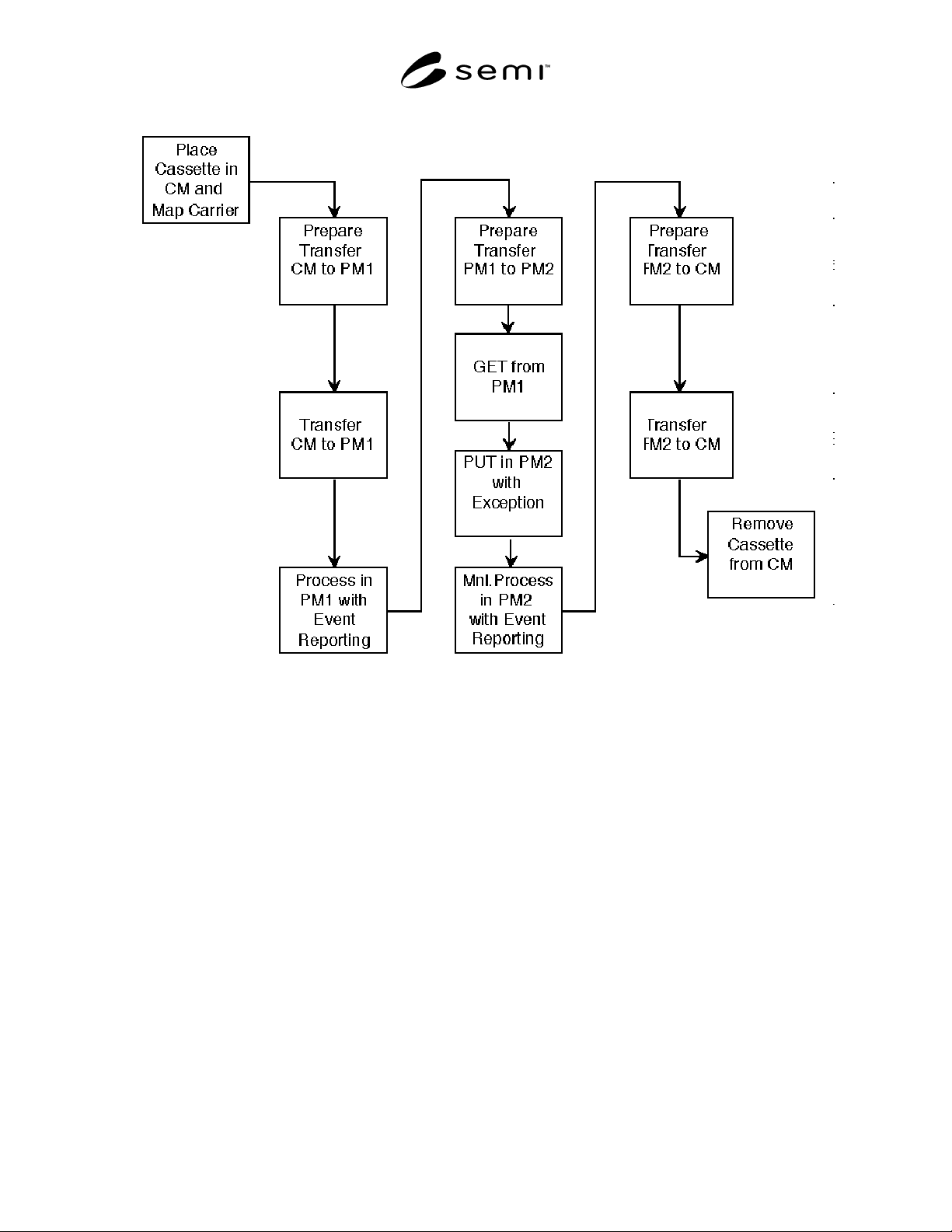
SEMI E38-1296 © SEMI 1995, 1996 32
Figure 20
Typical Operating Scenario
A1-2 Typical Operating Scenario
The purpose of this section is to give an example of a
typical operating scenario that will illustrate the various
services being used to perform cluster tool control
functionality. This operating scenario is NOT intended
to be the only scenario to be implemented in a
standards-compliant cluster. The intent is to provide
guidance in navigating the various services standards.
An exhaustive use of Object Services and Exception
Management Services will not be done since these two
areas tend to be very application-specific.
This scenario concentrates on the material processing,
material movement aspects of the cluster-specific
services.
The operating scenario shown in Figure 20 will be
given in the form of a communication timing diagram
with messages being sent between the various cluster
tool components and will be indicated in the following
manner:
ServiceGroup_ServiceName.Request or Response
(Service Parameters)
Example: TRJobCreate.Req(...)
• TR is the service group that contains the service,
the material movement services.
• JobCreate is the service being used to cause
communication to take place between two cluster
tool components. Specifically, this service is the
material movement service that initiates the
transfer of material between modules.
• Req indicates that the service is a Request.
• (...) indicates any other parameters that might be
present with the service definition and will be
service-dependent.
Definitions:
CC = Cluster Controller
CM = Cassette Module

SEMI E38-1296 © SEMI 1995, 199633
TM = Transport Module
PM1 = Processing Module #1
PM2 = Processing Module #2
The general routing for the scenario is illustrated in the
message sequence below:
1. A cassette of wafers arrives from the factory and is
given to the cassette module.
2. A mapping of the wafers in the various slots of the
cassette is determined for use inside the cluster.
3. A transfer job is initiated to move a wafer from the
cassette to a process module (in this case PM1).
4. The cassette module is commanded to send the
wafer to the transport module.
5. The PM1 is instructed to create the process job and
to retrieve any pertinent recipe information in order
to process the wafer.
6. The wafer is handed off between the cassette
module and the transport module (Wafer GET
operation).
7. The wafer is handed off between the transport
module and PM1 (this is a Wafer PUT operation).
8. The wafer is processed in PM1.
9. A transfer job is initiated to the transport module to
move a wafer from PM1 to PM2.
10. The PM1 is commanded to send the wafer to the
transport module.
11. The PM2 is instructed to create the process job and
to retrieve any pertinent recipe information in order
to process the wafer.
12. The wafer is handed off between the PM1 and the
transport module with a GET.
13. The wafer is handed off between the transport and
PM2 with a PUT.
14. The wafer is processed in PM2 when manually
started.
15. A transfer job is initiated to the transport module to
move a wafer from PM2 back to the cassette
module.
16. The PM2 is commanded to send the wafer to the
transport module.
17. The cassette module is instructed to receive the
wafer.
18. The wafer is handed off between PM2 and the
transport module.
19. The wafer is handed off between the transport
module and the cassette module.
20. The cassette module is instructed to send the
cassette to the factory.
1. FACTORY TO CM CASSETTE HANDOFF
The cassette containing a single wafer in wafer slot 1 to
be processed by the cluster tool is passed from the
factory environment to the cluster tool.
At this point the user (human or host) will be prompted
to place the cassette on the cassette module loading
system. The cassette module is then informed to receive
a cassette from the external environment.
CC CM
>>------------------------------------->>
TRJobCreate.Req(MID="Carrier1",Port=Port2
, Dir=Receive)
CC CM
<<-------------------------------------<<
TRJobCreate.Rsp(JobID=IOJob1,Status=OK)
The cassette module prepares to receive the cassette by
such actions as loadlock venting, door opening, and
then requesting handoff from the Factory.
CC CM
<<-------------------------------------<<
TRJobStarted.Req(JobID=IOJob1, TimeStamp)
The actual cassette transfer takes place, the cassette
module takes such actions as door closing and loadlock
pumping down to internal transfer pressures, and then
reports completion of the material transfer.
CC CM
<<-------------------------------------<<
TRJobComplete.Req(JobID=IOJob1,TimeStamp,
Status=OK))