semi合集-English.pdf - 第7215页
SEMI MF26-0305 © SEMI 2003, 2005 5 4.5.3 Calculate the instrum ent errors, and , as follows: 2 ) ( 3 1 (8) and 2 ) ( 4 2 (9) where is taken from Table 1 for the crystallogra phic…

SEMI MF26-0305 © SEMI 2003, 2005 4
4.2 Apparatus
4.2.1 X-Ray Apparatus, commercially available, utilizing a copper-target tube, gives satisfactory results. The X-ray
beam is collimated by means of a slit system to give parallel rays, and the X rays are passed through a thin nickel
filter to give a beam that is essentially monochromatic. The specimen is placed in a holder so that the surface under
investigation contains the axis about which the specimen is rotated in satisfying the Bragg law conditions. Rotations
about this axis are measured on a scale in degrees and minutes of arc. The holder must also permit rotation of the
specimen about a normal to the surface under investigation. The Bragg angle corresponding to the particular X-ray
wavelength used, the material under investigation, and the particular family of planes being oriented must be known
from Table 1 or be determined. A suitable detector, such as a Geiger counter, is positioned so that the angle
between the extension of the incident X-ray beam and the line joining the counter and the axis of rotation of the
specimen is twice the Bragg angle. It is essential that the incident X-ray beam, the diffracted beam, the reference
surface normal, and the detector opening all lie in the same plane.
4.3
Hazards
4.3.1 Too much emphasis cannot be placed on the necessity of avoiding personal exposure to X rays. It is
especially important to keep hands or fingers out of the path of the X rays and to protect the eyes from scattered
secondary radiation. The use of commercial film badge or dosimeter service is recommended together with periodic
checks of the radiation level at the hand and body positions with a Geiger-Müller counter calibrated with a standard
nuclear source. The present maximum permissible dose for total body exposure of an individual to external X
radiation of quantum energy less than 3 MeV over an indefinite period is 1.25 R (3.22 × 10
4
C/kg)/calendar quarter
(equivalent to 0.6 mR/h (1.5 × 10
7
C/kg·h)) as established in the Code of Federal Regulations, Title 10, Part 20.
The present maximum permissible dose for hand and forearm exposure under the same conditions is 18.75 R
(4.84 × 10
3
C/kg)/calendar quarter (equivalent to 9.3 mR/h (2.4 × 10
6
C/kg·h)).
4.4 Procedure
4.4.1 Adjust the surface under investigation about the axis of rotation perpendicular to the incident and reflected
beams until the diffracted intensity is at a maximum.
4.4.2 Record, to the nearest minute, as
1
, the angle indicated on the scale.
4.4.3 Rotate the specimen through 90° of arc about a normal to the (reference) surface under investigation. Repeat
the procedure of ¶4.4.1 and record, to the nearest minute, as
2
, the angle indicated on the scale.
4.4.4 Rotate the specimen another 90° of arc in the same direction (that is, 180° from the original position). Repeat
the procedure of ¶4.4.1 and record, to the nearest minute, as
3
, the angle indicated on the scale.
4.4.5 Rotate the specimen another 90° of arc in the same direction (that is, 270° of arc from the original position).
Repeat the procedure of ¶4.4.1 and record, to the nearest minute, as
4
, the angle indicated on the scale.
4.5 Calculations
4.5.1 Calculate and record the angular deviation components,
and
, as follows:
)(
2
1
31
(4)
and
)(
2
1
42
(5)
4.5.2 Calculate and record the total angular deviation,
, between the surface under consideration and the desired
crystallographic plane as follows:
coscoscos
(6)
where
and
are the two components of the total angular deviation,
. For angles smaller than 5° of arc, this
relationship may be simplified to the following:
222
(7)

SEMI MF26-0305 © SEMI 2003, 2005 5
4.5.3 Calculate the instrument errors,
and
, as follows:
2
)(
31
(8)
and
2
)(
42
(9)
where
is taken from Table 1 for the crystallographic plane and material under consideration.
NOTE 2: The instrument errors need not be recorded; however, if they remain small and constant, they can be used to correct
1
and
2
so that
and
can be determined from only two measurements when the highest precision is not required. Since the
instrument error is a constant,
and
should be the same. Any difference between
and
is due to inaccuracies in one's
ability to measure
1
,
2
,
3
, and
4
. With precise measurements, the difference between
and
should be less than ½ min.
5 Test Method B — Optical Orientation
5.1 Summary of Test Method
5.1.1 When a single crystal surface of germanium or silicon is lapped and preferentially etched, numbers of
microscopic pits appear on the crystal surface. These pits are bounded by planes related to the principal
crystallographic directions of the material. These limiting boundary planes determine the shape of the pits when the
etched surface is near a major crystallographic direction. An optical examination of the facets comprising the pit
walls relates the crystal surface under examination to this crystallographic direction, and further permits a
determination of the degree of misorientation of the surface from the crystallographic plane.
5.1.2
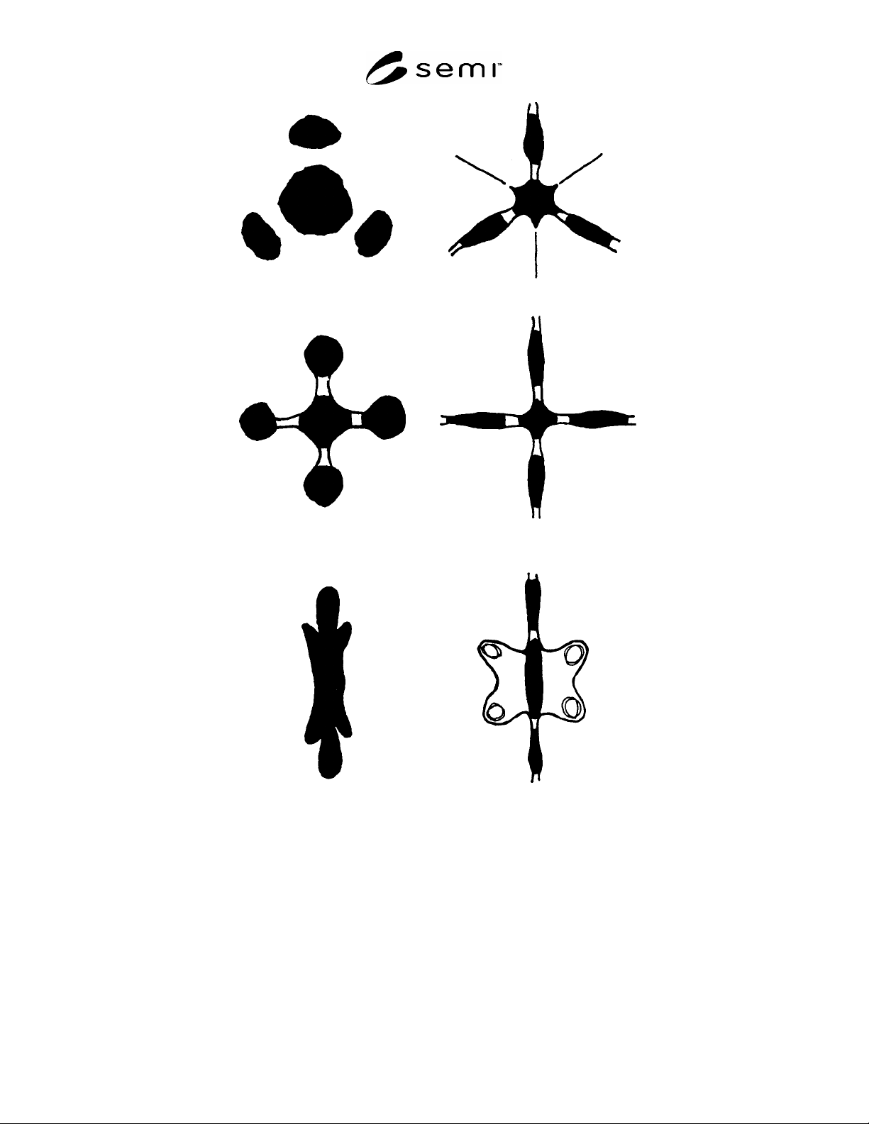
A light beam that is reflected from such a preferentially etched surface may be focused upon a screen to form
a definite geometric pattern characteristic of the surface etch pit structure. Patterns, such as those reproduced in
Figure 2, reflected from surfaces approximately parallel to (111)-, (100)-, and (110)-type planes are recognizable. In
each instance, the central portion of the pattern observed on the screen is the reflection from the bottom of the etch
pit. These bottom facets represent planes parallel to the characteristic crystallographic plane of the surface under
investigation. Therefore, when the central reflected beam is aligned with the direction of the light beam, this
crystallographic plane is perpendicular to the light beam direction. This observation permits orientation of the
crystal along a desired crystallographic axis or, alternatively, allows the determination of the degree of
misorientation of a crystal surface from a desired crystallographic plane.
5.2
Reagents and Materials
5.2.1 Purity of Water — Reference to water shall be understood to mean Type E-3 or better water as described in
ASTM Guide D 5127.
5.2.2
Germanium Etchant Solution — Mix 1 part HF, 1 part H
2
O
2
, and 4 parts water, by volume.
5.2.3 Hydrofluoric Acid (HF), 49%, in accordance with Grade 1 of SEMI C28.
5.2.4 Hydrogen Peroxide (H
2
O
2
), 30%, in accordance with Grade 1 of SEMI C30.
5.2.5 Potassium Hydroxide Solution (KOH), 45% by weight in water, in accordance with Grade 1 of SEMI C40.
5.2.6 Sodium Hydroxide Solution (NaOH), 50% by weight in water, in accordance with Grade 1 of SEMI C43.
5.3 Apparatus
5.3.1 Light Beam — originating preferably from a high-intensity point source. An image of the source shall be
observed on a screen following reflection from a front surface mirror occupying the crystal test position. This image
establishes the zero reference point. The angle of incidence at the reflecting surface may be 0° of arc, in which case
a hole must be provided at the center of the screen to permit passage of the incident light beam. The angle of
incidence may be made large enough to permit the screen to be displaced to one side of the light beam. In this
arrangement, it is essential that the screen be placed in the focal plane of the lens system to minimize distortion of
the image.
SEMI MF26-0305 © SEMI 2003, 2005 6
(
111
)
GERMANIUM
(110) GERMANIUM
(100) GERMANIUM
(100) SILICON
(110) SILICON
(111) SILICON
Figure 2
Optical Reflections from Etched Germanium and Silicon Surfaces
5.3.2 Stage — capable of rotation both vertically and horizontally and calibrated to permit measurements of
deviation from the 0° reference plane. Means shall be provided to securely position the reflecting surface of the
crystal on the stage of the apparatus.
5.4 Procedure
5.4.1 Abrade the specimen surface by lapping with No. 600 silicon carbide abrasive. The abrasive grain size
specified for this purpose shall comply with the appropriate specifications of ANSI B74.10. Care must be taken to
produce no angular deviation from the original surface during the lapping operation.