semi合集-English.pdf - 第2061页
SEMI E54.10-0600 © SEMI 2 000 6 8.2.1.5 Gain (Opti onal) — An attribu t e that specifies the Gain v alue of the amplifier for the photodiode sig - nal. The f actor y conf igured out-of-box value is deter- mined by the ma…
SEMI E54.10-0600 © SEMI 20005
Attribute Name Attribute Identifier Access Network Required Form
Leak Status A40 R No Byte, enumerated
Time Stamp A41 RW No Date_And_Time
Reserved A42–A64 — — Reserved for SDM future expansion
Manufacturer Specified > A64 — — Manufacturer Specific attributes
NOTE 1: “*” Indicates that the specific attribute is nonvolatile. Nonvolatile requires that the current attribute value be maintained through a
component power cycle.
8.2.1.1 Device Type — An attribute that uniquely
identifies the type of the device on the network. The
device type attribute is assigned as follows:
In-Situ Particle Monitor Device = “ISPM”
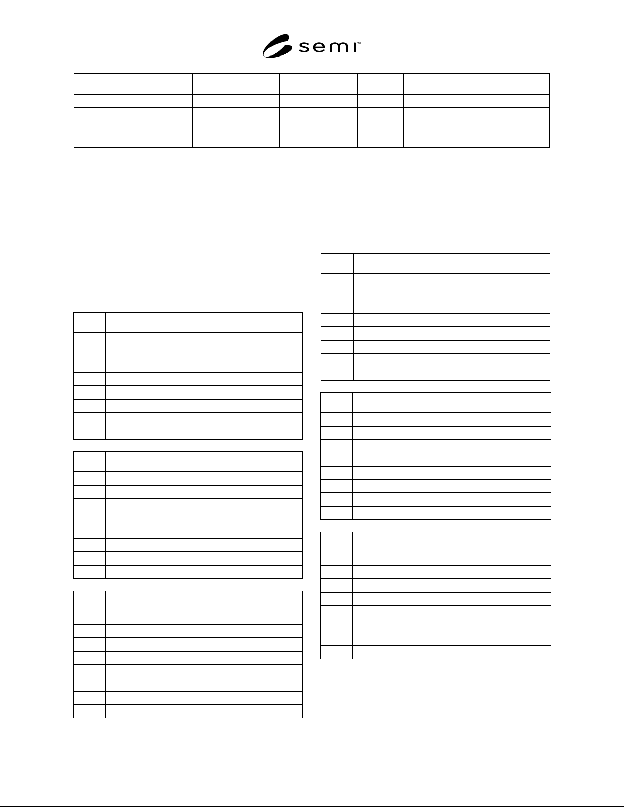
8.2.1.2 Exception Detail Alarm (Optional) — An
attribute which identifies the detailed alarm status of the
device. Table 4 defines the bit assignments associated
with the alarm exception detail.
Table 4 Exception Detail Alarm Bit Assignments
Bit Device Specific Alarm[0]
0 Reserved
1 Interlock
2 Sensor Not Detected
3 Leak Detected
4 Reserved
5 Sensor Type Changed
6 Reserved
7 Reserved
Bit Device Specific Alarm[1]
0 High Laser Current
1High Stray Light
2 High Median Noise
3 High Calibration
4 High Fill Rate
5 High Flow Rate
6 Reserved
7 Reserved
Bit Device Specific Alarm[2]
0 Low Laser Current
1Low Stray Light
2 Low Median Noise
3 Low Calibration
4 Low Fill Rate
5 Low Flow Rate
6 Reserved
7 Reserved
8.2.1.3 Exception Detail Warning (Optional) — An
attribute which identifies the detailed warning status of
the device. Table 5 defines the bit assignments
associated with the warning exception detail.
Table 5 Exception Detail Warning Bit Assignments
Bit Device Specific Warning[0]
0Reserved
10
20
30
4Reserved
50
6Reserved
7Reserved
Bit Device Specific Warning[1]
0 High Laser Current
1High Stray Light
2 High Median Noise
3 High Calibration
4 High Fill Rate
5 High Flow Rate
6Reserved
7Reserved
Bit Device Specific Warning[2]
0 Low Laser Current
1Low Stray Light
2 Low Median Noise
3 Low Calibration
4 Low Fill Rate
5 Low Flow Rate
6Reserved
7Reserved
8.2.1.4 Manufacturer Exception Detail Size (Optional)
— An attribute that specifies the number of exception
detail bytes included in the alarm or warning details.
SEMI E54.10-0600 © SEMI 2000 6
8.2.1.5 Gain (Optional) — An attribute that specifies
the Gain value of the amplifier for the photodiode sig-
nal. The factory configured out-of-box value is deter-
mined by the manufacturer based on the sensor type.
8.2.1.6 Filter Bandwidth (Optional) — An attribute
that determines the bandwidth in kilohertz of the
amplifier for the photodiode signal. The factory
configured out-of-box value is determined by the
manufacturer based on the sensor type.
8.2.1.7 Tool State (Optional) — An attribute that
identifies the current state of the tool that is utilizing the
counter. In many cases, the ISPM device can detect and
report the Tool State; this variable is utilized for this
type of reporting. This attribute is enumerated and is
specified by the manufacturer.
8.2.1.8 Laser Status — An attribute that records the
current status of the laser. This attribute is enumerated.
The possible enumeration and the requirement for
support are as follows:
0 = LASER OFF (required)
1 = LASER TURNING ON (optional)
2 = LASER ON BUT NOT STABLE (optional)
3 = LASER ON AND STABLE (required)
4 = LASER INTERLOCKED (optional)
5 = SENSOR MISSING (required)
6–63 = Reserved
64–255 = Manufacturer Specified (optional)
8.2.1.9 Flow Path (Optional) — An attribute that
identifies the current flow path (from multiple sources)
being utilized. The source may be modified by a Host at
anytime. Changing the “Flow path” attribute connects
the ISPM device to a different source. When changing
sources, data is not valid for a time interval whose
length is a function of the distance to the source.
8.2.1.10 Volume (Optional) — An attribute that
maintains the sample volume. This attribute is used
primarily by liquid particle counters utilizing a
sampling technique in a small container to extrapolate
the particle count in the volume of interest. The value
of this attribute is the size of the small container.
8.2.1.11 Volume Units (Optional) — An attribute that
specifies the unit for the “Volume” attribute. This
attribute is enumerated and can take on one of the
following values: milliliters or gallons. (See Appendix
1 of SEMI E54.1 for assigned values.)
8.2.1.12 Leak Status (Optional) — An attribute that
indicates which one of the potential leak locations is
actually leaking. This attribute is enumerated and is
specified by the manufacturer. The enumerated value
corresponds to a specific leak location.
8.2.1.13 Time Stamp (Optional) — An attribute that
records the time when the last counting event
completed.
8.2.1.14 Duration (Optional) — An attribute that
defines the interval of time during which the particle
counts are collected and put into the bin assemblies.
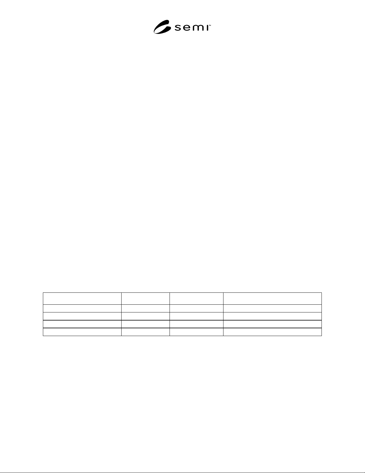
8.2.1.15 Initial and Default Values
Table 6 DM Object Attribute Initial and Default Values
Attribute Initial Value Default Value Comment
Device Type ISPM ISPM ISPM = In-Situ Particle Monitor Device
Exception Detail Alarm 0 0
Exception Detail Warning 0 0
Laser Status 0 0 Laser Off
SEMI E54.10-0600 © SEMI 20007
8.2.2 Device Manager Object Services — The services provided by the Device Manager object are defined in
SEMI E54.1 [1]. The Device Manager object supports the additional services listed below.
Table 7 Device Manager Object Services
Service Service Identifier Type Description
Laser On S1 R Used to prompt the device to take the laser from the
LASER OFF state to LASER ON AND STABLE state as
defined by the Laser Status attribute.
Laser Off S2 R Used to prompt the device to take the laser immediately to
the LASER OFF state as defined by the Laser Status
attribute.
Reserved S3–S64 — Reserved for future expansion
Manufacturer Specified > S64 — Manufacturer Specific services
8.2.2.1 Laser On (Optional) — This service is used to prompt the device to take the laser from the LASER OFF
state through supported laser states 1 and/or 2, to state 3, as defined by the Laser Status attribute. If the laser turns on
successfully, a “success” response code is returned. If the sensor is missing or interlocked off, a “object state
conflict” error response is returned and the laser remains in the appropriate state.
8.2.2.2 Laser Off (Optional) — This service is used to prompt the device to take the laser to the LASER OFF state
immediately. If the laser turns off successfully, a “success” response is returned. If the sensor is in an interlocked
state, a “object state conflict” error response is returned and the laser remains in the interlocked off state.
8.2.3 Device Manager Object Behavior — The behavior exhibited by the Device Manager object is defined in
SEMI E54.1 [1]. Additional behavior is detailed below.
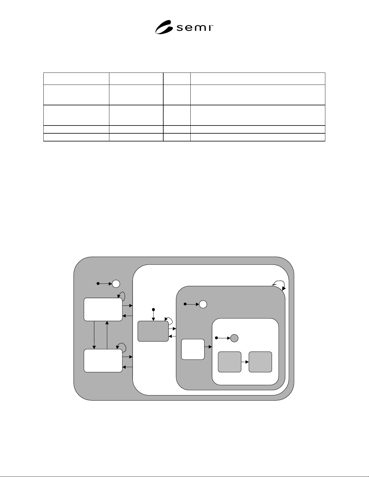
8.2.3.1 Device Manager EXECUTING State Behavior — Required sub-states within the EXECUTING state,
descriptions of these substates, and a transition matrix associated with these sub-states are given in Figure 2, Table
8, and Table 9 respectively.
LASER
INTERLOCKED
SENSOR
MISSING
EXECUTING
C
1
2
3
4
5
10
11
6
7
LASER
OFF
12,13
8
9
LASER NOT OFF
LASER
TURNING
ON
C
15
16
LASER ON
LASER
ON AND
STABLE
LASER
ON AND
NOT
STABLE
18
C
17
LASER ADDRESSABLE
14
Figure 2
Device Manager Object Behavior Within the EXECUTING State