semi合集-English.pdf - 第312页
SEMI E48-1101 © SEMI 1995 , 2001 1 SEMI E48-1101 SPECIFICA TION FOR SMIF INDEXER VOLU ME REQUIREMENT This specific ation was techn ically appr oved by the Glob al Physical Interfaces & Carri ers Committee an d is the…

SEMI E47.1-0305 © SEMI 1997, 2005 26
NOTICE: SEMI makes no warranties or representations as to the suitability of the standards set forth herein for any
particular application. The determination of the suitability of the standard is solely the responsibility of the user.
Users are cautioned to refer to manufacturer's instructions, product labels, product data sheets, and other relevant
literature, respecting any materials or equipment mentioned herein. These standards are subject to change without
notice.
The user’s attention is called to the possibility that compliance with this standard may require use of copyrighted
material or of an invention covered by patent rights. Entegris, Inc. has filed a statement with SEMI asserting that
licenses will be made available to applicants throughout the world for the purpose of implementing this standard
without unfair discrimination. Attention is also drawn to the possibility that some elements of this standard may be
subject to patented technology or copyrighted items other than those identified above. Semiconductor Equipment
and Materials International (SEMI) shall not be held responsible for identifying any or all such patented technology
or copyrighted items. By publication of this standard, SEMI takes no position respecting the validity of any patent
rights or copyrights asserted in connection with any item mentioned in this standard. Users of this standard are
expressly advised that determination of any such patent rights or copyrights and the risk of infringement of such
rights are entirely their own responsibility.
Copyright by SEMI® (Semiconductor Equipment and Materials
International), 3081 Zanker Road, San Jose, CA 95134. Reproduction of
the contents in whole or in part is forbidden without express written
consent of SEMI.
SEMI E48-1101 © SEMI 1995, 20011
SEMI E48-1101
SPECIFICATION FOR SMIF INDEXER VOLUME REQUIREMENT
This specification was technically approved by the Global Physical Interfaces & Carriers Committee and is
the direct responsibility of the European Equipment Automation Committee. Current edition approved by the
European Regional Standards Committee on April 24, 2001. Initially available at www.semi.org August
2001; to be published November 2001. Originally published in 1995; previously published July 2001.
1 Purpose
1.1 The purpose of this specification is to provide the
volume required within a tool that enables integration
of SMIF into tools with single or multiple ports.
2 Scope
2.1 This specification defines the space necessary
within a tool with respect to the interface plane. The
specification refers to the Standard Mechanical
InterFace (SMIF) Standard, SEMI E19.
2.2 This standard does not purport to address safety
issues, if any, associated with its use. It is the
responsibility of the users of this standard to establish
appropriate safety and health practices and determine
the applicability of regulatory limitations prior to use.
3 Referenced Standards
3.1 SEMI Standards
SEMI E15 — Specification for Tool Load Port
SEMI E19 — Standard Mechanical Interface (SMIF)
NOTE 1: As listed or revised, all documents cited shall be the
latest publications of adopted standards.
4 Terminology
4.1 cassette — an open structure that holds one or
more substrates (e.g., wafers, masks).
4.2 integrated SMIF — a unit including a SMIF port
and a mechanism for indexing the port door. The entire
unit being incorporated within the tool.
4.3 standard mechanical interface (SMIF) — the
interface plane between a pod and another
minienvironment per SEMI E19.
4.4 wafer transfer plane — a plane with a maximum
distance from the interface plane to the level where a
wafer can be transferred.
5 Requirements
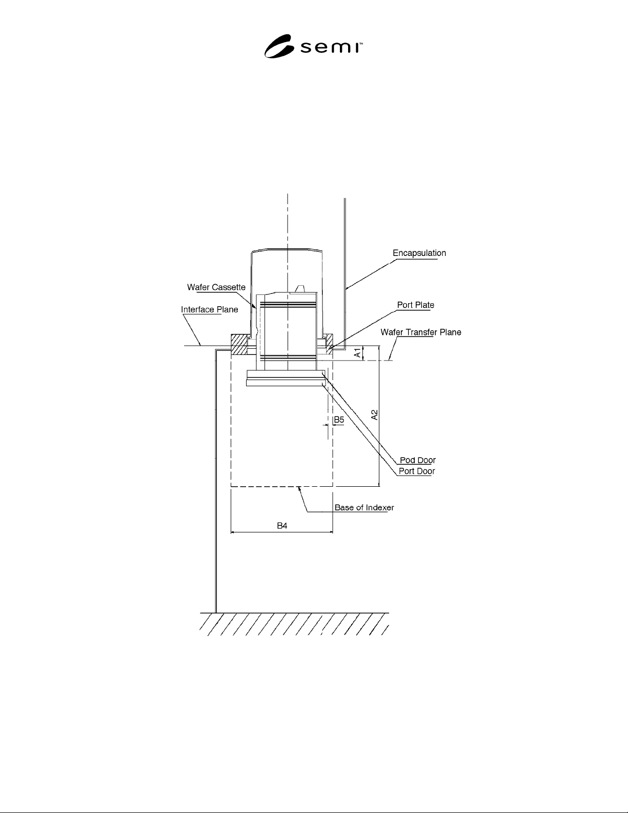
5.1 Figure 1 depicts the height dimensions and
terminology for integrated SMIF. Figure 2 shows the
necessary footprint for the integrated SMIF on a tool.
The dimensions are given with reference to SEMI E15.
5.2 The minimum distance between the interface plane
and the wafer transfer plane A1 is limited by the
thickness of the port plate and any wafer sensing
system. This distance should be kept as small as
possible for ergonomic reasons.
5.3 The dimension A2 below the interface plane takes
into account the distance A1, the cassette dimensions,
and the mechanical components. Process tools must
provide this free space to allow integration of SMIF.
5.4 Referring to Figure 2, it can be seen that the axis
of the wafer transfer, B2, does not necessarily
correspond to the center line of the integrated SMIF
unit. This is to allow the indexing mechanism to be
placed in different locations, so that multiple ports can
be furnished, still adhering to SEMI E15.
Table 1 Integrated SMIF Dimensions
Up to 150 mm 200 mm
Installation Height A1 63 mm max.
(2.48" max.)
63 mm max.
(2.48" max.)
A2 400 mm min.
(15.75" min.)
400 mm min.
(15.75" min.)
Footprint B1 355 mm min.
(13.98" min.)
355 mm min.
(13.98" min.)
B2 177.5 mm max.
(6.99" max.)
177.5 mm max.
(6.99" max.)
B3 157 mm max.
(6.18" max.)
182 mm max.
(7.17" max.)
B4 390 mm min.
(15.35" min.)
390 mm min.
(15.35" min.)
B5 20 mm max.
(0.79" max.)
20 mm max.
(0.79" max.)
SEMI E15
(Recommendation)
S 350 mm
(13.8")
400 mm
(15.7")
Dimension Definitions
A1 — Maximum distance from the SMIF interface
plane to the wafer transfer plane.
A2 — Minimum depth, from the interface plane,
required in a tool.
B1 — Minimum width required in a tool.
SEMI E48-1101 © SEMI 1995, 2001 2
B2 — Maximum distance from the side of the indexer unit to the cassette or container centroid.
B3 — Maximum distance from the front of the indexer unit to the cassette or container centroid.
B4 — Minimum breadth required for the indexer unit in a tool.
B5 — Maximum distance that can be penetrated underneath the port plate.
S — Recommended minimum spacing between cassette or container controids.
Figure 1
Integrated SMIF Side View