semi合集-English.pdf - 第1007页
SEMI E136-1104 © SEMI 2004 5 9.3.9 Testing — With the connections m ade according to Figure 2, apply main power to t he RF generator an d allow 15 minutes for stabilization . The power reading obtained on the calorimeter…
SEMI E136-1104 © SEMI 2004 4
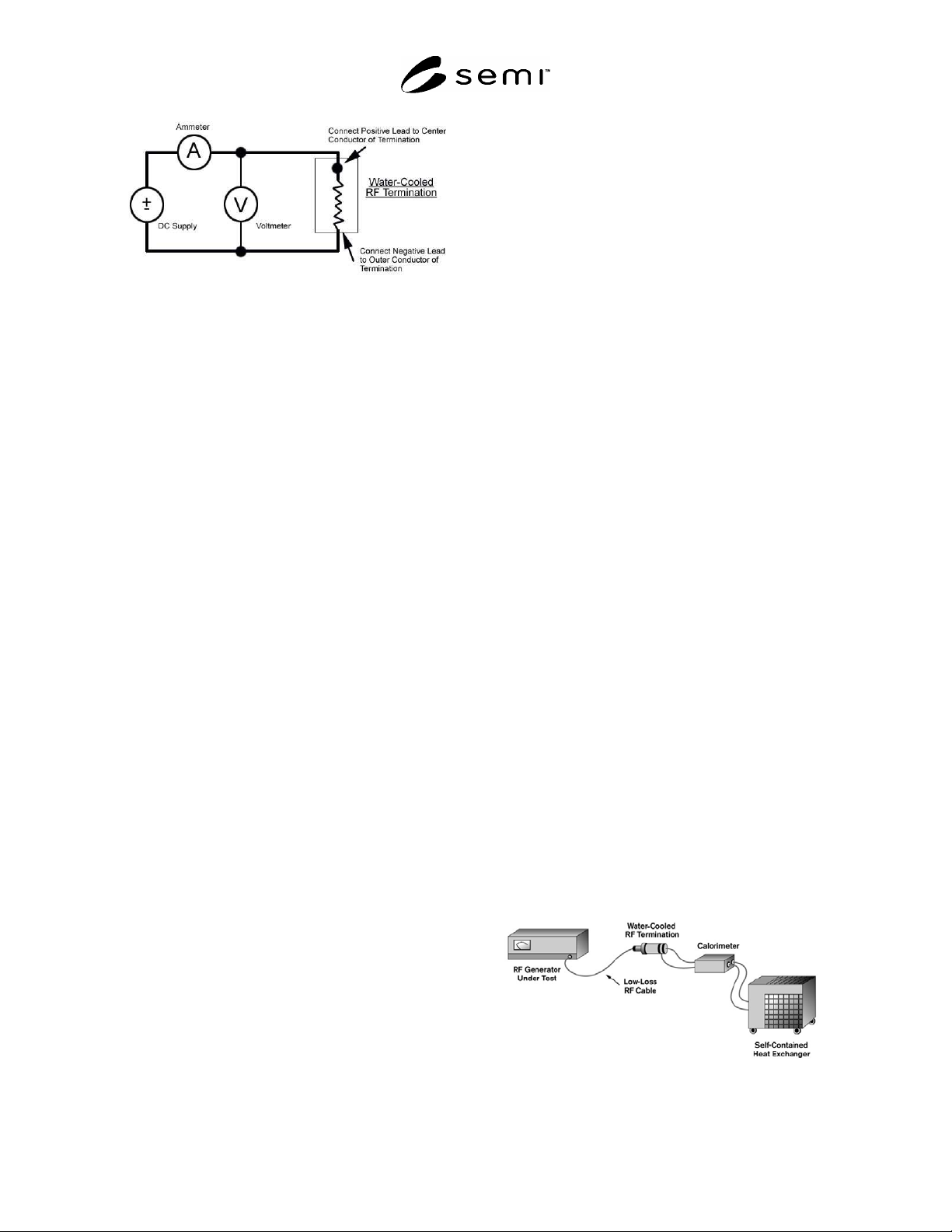
Figure 2
Calorimeter Calibration Connection Diagram
9.3.1 Use a calorimeter equipped with a coolant
system.
NOTE 5: Most calorimeter systems use either a tap-water
coolant system or a recirculating system of some type. Best
results may be obtained through the use of a self-contained
heat exchanger and coolant recirculating system.
9.3.2 Make all of the electrical and coolant connections
to the calorimeter.
9.3.3 Apply main power to the calorimeter system and
allow one hour for stabilization.
9.3.4 Load Differential Temperature — Most
calorimeter systems will yield optimum performance
when certain operating parameters relating to the
differential temperature across the RF load and the flow
rate are maintained. In most cases, a differential
temperature of 2°C represents a good beginning point.
The coolant flow rate may then be set to provide for
this differential temperature.
9.3.4.1 The following formula may be used to arrive at
the correct coolant flow rate.
Power = 69.32 ×
T × Flow Rate (1)
where:
Power is in W,
T is in C, and
Flow Rate is in L/min.
9.3.4.2 Solving for flow rate yields:
Flow Rate = (Power / 69.32) /
T (2)
9.3.5 Coolant Types — In most cases, the coolant used
in calorimetric power measurement systems is pure
distilled water. In this case, most modern calorimeters
will automatically correct for changes to the coolant
physical characteristics (e.g., specific heat, specific
gravity) as the coolant temperature changes.
9.3.5.1 If coolant other than pure water is used and the
calorimeter chosen will not automatically compensate
for changes to the coolant, adjust the power readings
obtained for the effects of the coolant changes. Consult
the calorimeter operating manual for specific details.
9.3.6 Calorimeter Calibration — Following the
calorimeter warm-up, the device is ready for
calibration.
9.3.6.1 With the calorimeter operating at the
appropriate flow rate, apply DC power to the RF load,
according to the voltage and current readings obtained
with the two digital multimeters.
9.3.6.2 Multiply the voltage reading by the current
reading to obtain the power applied to the load.
9.3.6.3 Allow 15 minutes for the calorimeter reading to
stabilize.
9.3.6.4 Using the procedure in the calorimeter
operating manual, set the calorimeter such that the
calorimeter reading is exactly the same as that obtained
using the voltage and current meters.
9.3.6.5 At this point, add any offsets that are associated
with interconnecting cable losses, as outlined in
Sections 6.5.2 and 6.5.3.
9.3.6.6 The calorimeter is now calibrated at this
specific power level.
NOTE 6: If a new power level is selected, repeat this process
in order to compensate for instrumentation linearity effects of
the calorimeter.
9.3.7 RF Generator Testing — With the calorimeter
calibrated at a particular power level, it is now possible
to test the RF generator power output at this level.
9.3.8 Connections — Connect the RF generator output
to the RF load according to Figure 3. Use cables and
connectors between the RF generator output and the RF
load of a high-quality, low-loss type. As outlined
above, some power will be lost in the cables between
the generator and the load. Add these losses as offsets
to the calorimeter reading, in order to obtain the total
power output of the generator. Base the losses upon
cable length, cable type, and operating frequency. See
SEMI E114 test method for details on cable loss
compensation.
Figure 3
RF Generator Output Power Test

SEMI E136-1104 © SEMI 2004 5
9.3.9 Testing — With the connections made according
to Figure 2, apply main power to the RF generator and
allow 15 minutes for stabilization. The power reading
obtained on the calorimeter will represent the total
power output of the RF generator, including harmonics.
9.3.9.1 Begin RF generator testing at a power level that
represents 10% of the maximum output power of the
RF generator.
9.3.9.2 Repeat the test at RF generator power levels of
40% of maximum, 70% of maximum, and maximum
power.
9.3.9.3 Also, conduct tests corresponding to each range
on the RF generator power output meter.
NOTE 7: Calibrate the calorimeter power meter to the DC
standard at each power level used.
NOTICE: SEMI makes no warranties or
representations as to the suitability of the standards set
forth herein for any particular application. The
determination of the suitability of the standard is solely
the responsibility of the user. Users are cautioned to
refer to manufacturer's instructions, product labels,
product data sheets, and other relevant literature,
respecting any materials or equipment mentioned
herein. These standards are subject to change without
notice.
By publication of this standard, Semiconductor
Equipment and Materials International (SEMI) takes no
position respecting the validity of any patent rights or
copyrights asserted in connection with any items
mentioned in this standard. Users of this standard are
expressly advised that determination of any such patent
rights or copyrights, and the risk of infringement of
such rights are entirely their own responsibility.
Copyright by SEMI® (Semiconductor Equipment and Materials
International), 3081 Zanker Road, San Jose, CA 95134. Reproduction of
the contents in whole or in part is forbidden without express written
consent of SEMI.

SEMI E137-1104 © SEMI 2004 1
SEMI E137-1104
GUIDE FOR FINAL ASSEMBLY, PACKAGING, TRANSPORTATION,
UNPACKING, AND RELOCATION OF SEMICONDUCTOR
MANUFACTURING EQUIPMENT
This guide was technically approved by the Global Gases Committee and is the direct responsibility of the
North American Gases Committee. Current edition approved by the North American Regional Standards
Committee on July 11, 2004. Initially available at www.semi.org September 2004; to be published
November 2004.
NOTICE: This standard replaces SEMI E49.1, which has been removed from publication as of the November 2004
(1104) publication cycle.
1 Purpose
1.1 The objective of this document is to establish
standard guidelines for activities specific to the final
assembly, packaging, transportation, unpacking, and
relocation of semiconductor manufacturing equipment
(SME) to the cleanroom manufacturing area.
2 Scope
2.1 This standard has been developed as a guide for
final assembly through relocation of SME, separate
subassemblies, and components from the customer’s
loading dock/receiving area to their cleanroom
manufacturing area for both high and ultrahigh purity
applications.
NOTICE: This standard does not purport to address
safety issues, if any, associated with its use. It is the
responsibility of the users of this standard to establish
appropriate safety and health practices and determine
the applicability of regulatory or other limitations prior
to use.
3 Limitations
3.1 Specific guidance associated with environment,
health, and safety (EHS) concerns are not in the scope
of this document.
NOTE 1: The SEMI EHS Technical Committee is working
on a new related safety guideline document that provides EHS
considerations for SME preparation, packaging, shipping, and
handling including the handling of shipping and packaging
materials.
3.2 Process specifications related to wafer particles
and/or quality (e.g., ionic contamination) are not in the
scope of this document. Parameters, such as particles
per wafer pass (PWP), should be in the customer’s
specific equipment process performance specification.
4 Referenced Standards
4.1 SEMI Standards
SEMI C41 — Specifications and Guidelines for 2-
Propanol
SEMI F63 — Guidelines for Ultrapure Water Used in
Semiconductor Processing
4.2 ISO Standard
1
ISO 14644-1 — Cleanrooms and Associated Controlled
Environments, Part 1: Classification of Air Cleanliness
4.3 APA The Engineered Wood Association
2
NOTE 2: The APA Engineered Wood Association was
formerly known as the American Plywood Association.
PS 1 — Voluntary Product Standard for Construction
and Industrial Plywood
4.4 USA Department of Defense (DOD)
3
MIL-D-3464 — Military Specification – Desiccants,
Activated, Bagged, Packaging Use and Static
Dehumidification
MIL-PRF-131 — Performance Specification – Barrier
Materials, Watervaporproof, Greaseproof, Flexible,
Heat-sealable
1 International Organization for Standardization, ISO Central
Secretariat, 1, rue de Varembé, Case postale 56, CH-1211 Geneva 20,
Switzerland. Telephone: 41.22.749.01.11; Fax: 41.22.733.34.30,
Website: /www.iso.ch
2 APA-The Engineered Wood Association, 7011 So. 19th, Tacoma,
WA 98466, (253) 565-6600, Fax: (253) 565-7265 Website:
http://www.apawood.org
3 United States of America (USA) Department of Defense (DOD)
ASSIST Quick-Search, Website:
http://www.dodssp.daps.mil/products.htm