semi合集-English.pdf - 第937页
SEMI E119-1104 © SEMI 2002, 2004 9 5.9 Hum an Handles — All handles for use by humans must either be contained within the maxim u m outer dimensions o f the FOBIT, be detache d when not in use , or be retracta ble into t…
SEMI E119-1104 © SEMI 2002, 2004 8
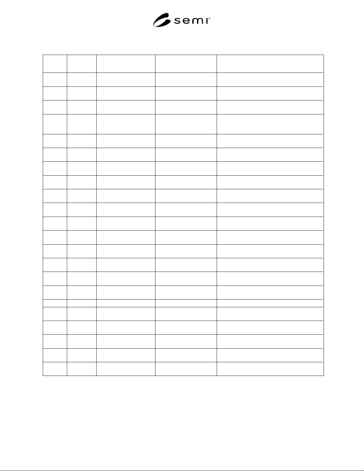
Table 1 Internal FOBIT Dimensions (Figures 15)
Symbol
Used
Figure
Number
Value Specified
Datum Measured from
Boundary or Feature Measured to
r1 1 151 mm (5.94 in.)
maximum
nominal wafer centerline outer edge of wafer pick-up volume
r2 1, 4 152 = + 1/– 0 mm
(5.98 + 0.04 – 0 in.)
y1 in front of nominal
wafer centerline
encroachment of FOBIT side domains on
wafer set-down volume
r3 1, 4 r2 + 1 mm (0.04 in.)
minimum
y1 in front of nominal
wafer centerline
encroachment of FOBIT side domains on
wafer extraction volume
r4 1 170 mm (6.69 in.)
minimum
nominal wafer centerline encroachment of FOBIT on end effector
exclusion zone between front and rear FOBIT
side domains
x1 1, 3 50 mm (1.97 in.)
minimum
bilateral datum plane inside of rear FOBIT side domains
x2 1, 3 75 mm (2.95 in.)
maximum
bilateral datum plane outside of rear FOBIT side domains
x3 1, 3, 4, 5 125 mm (4.92 in.)
minimum
bilateral datum plane inside of front FOBIT side domains
x51 1 140 mm (5.51 in.)
minimum
bilateral datum plane interior of FOBIT sides between y11 and y49
x52 1 170 mm (6.69 in.)
minimum
bilateral datum plane interior of FOBIT sides between y49 and y52
y1 1 3 mm (0.12 in.)
maximum
facial datum plane origin of r2 and r3 on bilateral datum plane
y5 1, 2 120 mm (4.72 in.)
minimum
facial datum plane front of rear FOBIT side domains
y11 1 85 mm (3.35 in.)
maximum
facial datum plane interior of FOBIT sides between x3 and x51
y20
#1
None 158 mm (6.22 in.) facial datum plane maximum protrusion of wafers toward the
front of the FOBIT
y49 1 134 mm (5.28 in.)
maximum
facial datum plane interior of FOBIT sides between x51 and x52
y51 1, 6, 8 140 mm (5.51 in.)
minimum
facial datum plane rear of door
z6 2, 3, 5 28.5 mm (1.12 in.)
maximum
horizontal datum plane top of FOBIT bottom domain
z8 2, 3, 5 35 mm (1.38 in.) horizontal datum plane bottom nominal wafer seating plane
z10 4 0 ± 0.5 mm
(0.00 ± 0.02 in.)
each nominal wafer
seating plane
entire bottom of the wafer
z11 4 2.9 mm (0.11 in.)
minimum
each nominal wafer
seating plane
encroachment of FOBIT side domains on
clearance above the wafer
z12 2, 3, 4, 5 6.25 mm (0.25 in.)
nominal
each nominal wafer
seating plane
adjacent nominal wafer seating planes
z15 2, 3, 4 4.6 mm (0.18 in.)
minimum
top nominal wafer
seating plane
bottom of FOBIT top domain
z23 4 1.5 mm (0.06 in.)
maximum
each nominal wafer
seating plane
bottom of wafer extraction volume
#1
These dimensions are for optional features.
5.8 External Dimensions — Figures 6 through 8 and
Figure 10 show the side, rear, top, and bottom views for
the FOBIT, respectively. Table 2 defines all of these
dimensions. In this and following figures, the heaviest
lines are used for surfaces that have tolerances (not
surfaces that have only maximum or minimum
dimensions). If an identification tag is used, it must be
located at the bottom rear centered on the bilateral
datum plane and must be contained within the
maximum outer dimensions of the FOBIT.
SEMI E119-1104 © SEMI 2002, 2004 9
5.9 Human Handles — All handles for use by humans
must either be contained within the maximum outer
dimensions of the FOBIT, be detached when not in use,
or be retractable into the maximum outer dimensions
when not in use. Although such handles may extend
past x53, they must still be contained within the upper
limits of x50, y40, and r67. Handles for use by humans
(if present) must follow SEMI S8, and they must
require the use of both hands (each using a full wrap-
around grip, given the minimum clearance requirement
in SEMI E15.1). Automation handling features shall not
be considered dual purpose unless they are designed to
meet SEMI S8 guidelines.
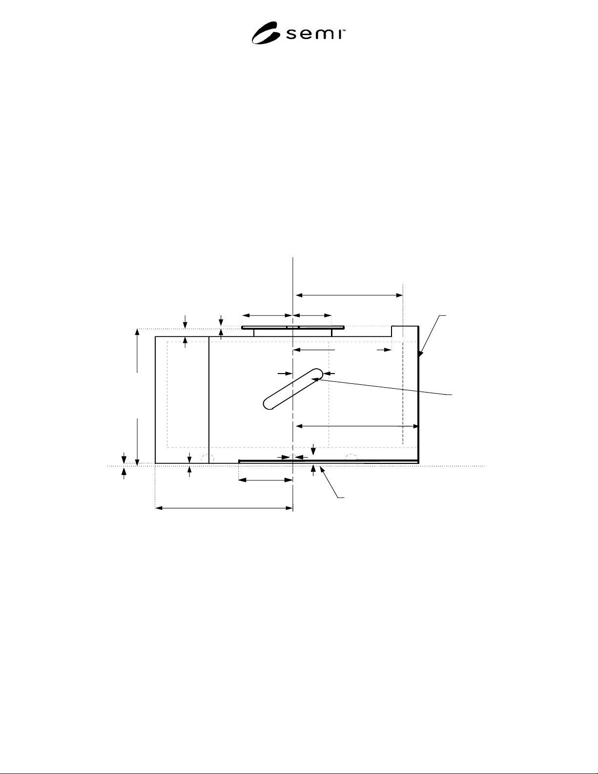
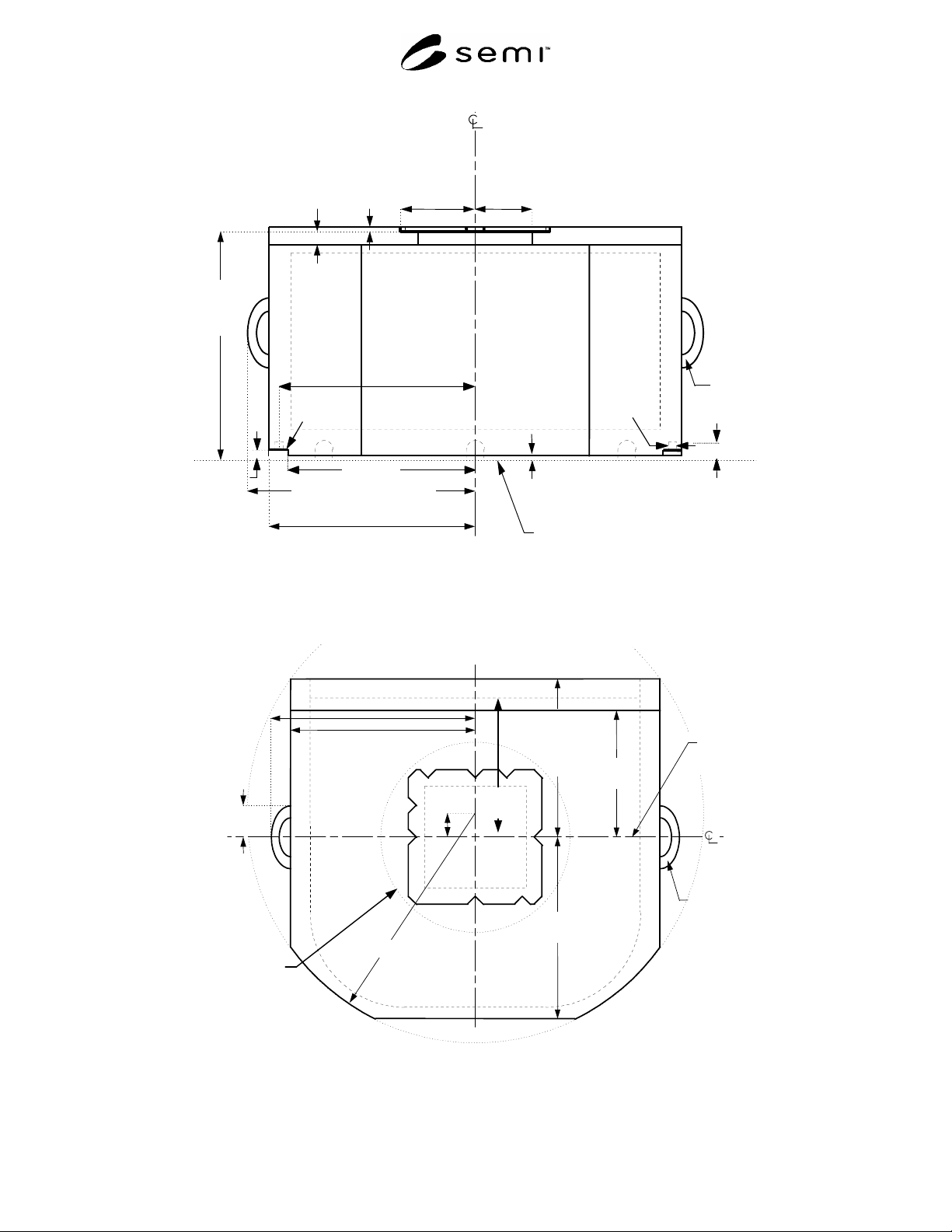
5.10 Automation Handling Features — On the top of
the FOBIT, there is an optional robotic handling flange
for manipulating the FOBIT as illustrated in Figure
9n the bottom of the FOBIT, there are optional rails
for use with roller conveyors or forklifts as shown in
Figures 6, 7 and 10. Although they are only required to
extend y58 behind the facial datum plane on both the
left and right sides, it is recommended that they be as
long as possible. Beyond y58, only the lower bound on
z43 applies. These optional conveyor rails (defined by
x56, x57, y58, and z43) are located on the left and right
bottom edges of the front-opening box and also have
vertical cylindrical pin holes for forklift centering
(defined by d65).
y51
140
facial
datum plane
horizontal datum of
box nest or load
port plane
y53
190
y50
130
y46
= 71 ± 1
y44
53
z49
8
z48
15
z47
= 221
± 1
y40
116
human
handle
(optional)
front side
of the
FOBIT
where
wafers
are
accessed
y
58 75
z41
0
d65 = 10 ± 0.5
z65
7
z43 = 2±1
y52 = 165.5 ± 0.5
(at seal zones, etc.)
166 (elsewhere)
Figure 6
Side View of FOBIT
SEMI E119-1104 © SEMI 2002, 2004 10
bilateral datum plane
horizontal datum plane of
box nest or load port
x
53
195 (elsewhere)
x
46
= 71 ± 1
x
44
53
z
49
8
z
48
15
z
47
= 221
± 1
human
handle
(optional)
z
41
0
z
43 = 2 ± 1
bottom rail
x
57
180
d65
= 10 ± 0.5
z
65 7
x
65 = 187.5
x
56 = 194.75
0.25
(
at bottom rail
)
x
50
215 (at human handle)
Figure 7
Rear View of FOBIT
Top robotic
flange detail
in Figure 9
human
handle
(optional)
y53
190
y52 = 165.5 ± 0.5
(at seal zones,
etc.)
166
(elsewhere)
bilateral
datum plane
front side of the FOBIT where wafers are accessed
y50
130
x
50
215 (at human handle)
x
53
195 (elsewhere)
r
67
240
facial
datum
plane
y 40
116
y67
= 25
y51
140
Figure 8
Top View of FOBIT