semi合集-English.pdf - 第4808页
SEMI C59-1104 © SEMI 2002, 2004 1 SEMI C59-1104 SPECIFICATIONS AND GU IDELINES FOR NITROGEN This specification was technically approved b y the Globa l Gases Com mittee and is the direct responsibility of the North Ameri…
SEMI C58-0305 © SEMI 2005 8
10.6.4.3 Introduce the span gas standard in hydrogen and, using the span adjust knob, set the needle (or output
reading) to match the level of hydrocarbons in the span gas.
10.6.4.4 Repeat ¶10.6.4.2 and ¶10.6.4.3 until reproducibility of readings is better than 1% of full scale.
10.6.4.5 Introduce hydrogen sample into the analyzer and read the quantity of hydrocarbons on the analyzer meter.
The result may not exceed the specification in Table 1 of this standard.
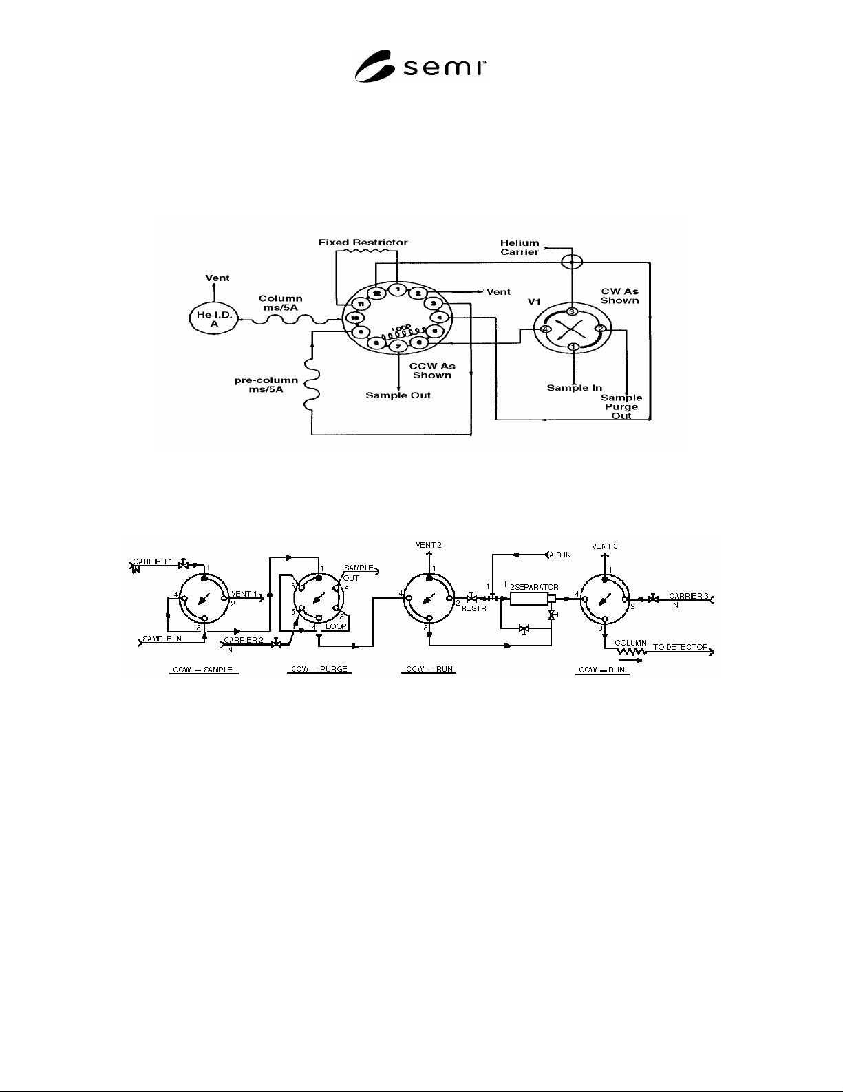
Figure 1
Analysis of Nitrogen
Figure 2
Flow Diagram for Discharge Ionization Detector Gas Chromatograph
with Integral Hydrogen Separator
NOTICE: SEMI makes no warranties or representations as to the suitability of the standards set forth herein for any
particular application. The determination of the suitability of the standard is solely the responsibility of the user.
Users are cautioned to refer to manufacturer's instructions, product labels, product data sheets, and other relevant
literature, respecting any materials or equipment mentioned herein. These standards are subject to change without
notice.
By publication of this standard, Semiconductor Equipment and Materials International (SEMI) takes no position
respecting the validity of any patent rights or copyrights asserted in connection with any items mentioned in this
standard. Users of this standard are expressly advised that determination of any such patent rights or copyrights, and
the risk of infringement of such rights are entirely their own responsibility.
Copyright by SEMI® (Semiconductor Equipment and Materials
International), 3081 Zanker Road, San Jose, CA 95134. Reproduction of
the contents in whole or in part is forbidden without express written
consent of SEMI.
SEMI C59-1104 © SEMI 2002, 2004 1
SEMI C59-1104
SPECIFICATIONS AND GUIDELINES FOR NITROGEN
This specification was technically approved by the Global Gases Committee and is the direct responsibility of
the North American Gases Committee. Current edition approved by the North American Regional Standards
Committee on July 11, 2004. Initially available at www.semi.org September 2004; to be published
November 2004. Originally published in November 2002; previously published November 2003.
1 Purpose
1.1 The purpose of this document is to provide a series
of specifications for different grades of Nitrogen (N
2
)
that are used in the semiconductor industry.
2 Scope
2.1 This document covers requirements for all grades
of nitrogen used in the semiconductor industry.
2.2 If analytical methods are not complete, the
requirements are presented as a guideline.
NOTICE: This standard does not purport to address
safety issues, if any, associated with its use. It is the
responsibility of the users of this standard to establish
appropriate safety and health practices and determine
the applicability of regulatory or other limitations prior
to use.
3 Description
3.1 Nitrogen is an odorless, tasteless, noncombustible
diatomic gas comprising approximately 78% of the
earth’s atmosphere; at cryogenic temperatures it is a
colorless liquid. Noncombustible; a cryogenic gas
derived from liquid air by fractional distillation.
4 Limitations
4.1 None.
5 Referenced Standards
5.1 SEMI Standards
SEMI C1 — Specifications for Reagents
SEMI C3 — Specifications for Gases
NOTICE: Unless otherwise indicated, all documents
cited shall be the latest published versions.
6 Terminology
6.1 Terminology appropriate to this standard is defined
in SEMI C3.
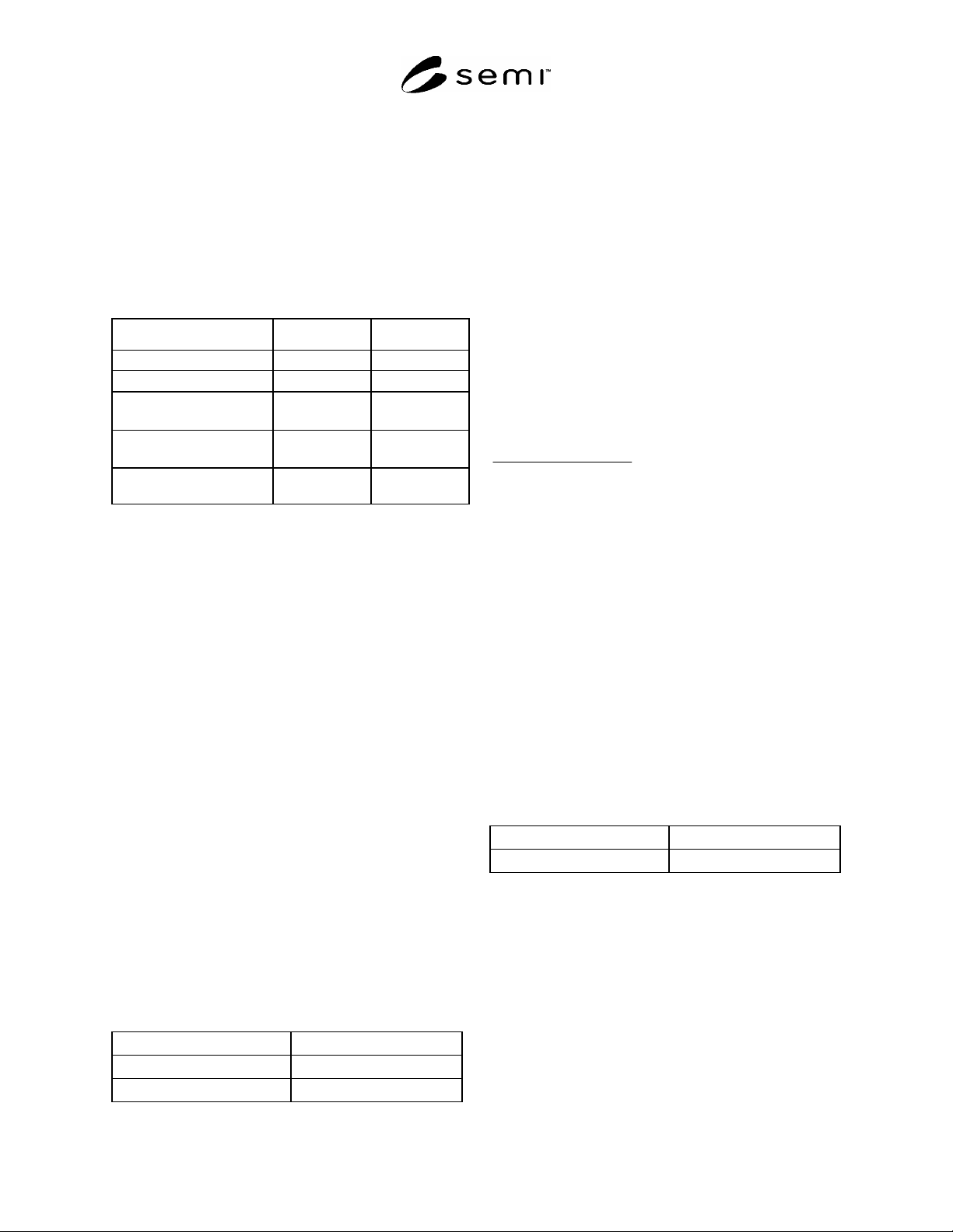
Table 1 Impurity and Other Requirements for Various Grades of Nitrogen
Previous SEMI Reference #
C3.5-93
(Specification)
C3.15-93
(Specification)
C3.48-0200
(Specification)
C3.29-96
(Specification)
C3.28-0200
(Guideline)
C3.49-94
(Specification)
Grade 4.8 5.2 5.4 5.5 5.6 7.0
Purity 99.998% 99.9992% 99.9994% 99.9995%
#1
99.9996% 99.99999%
Impurities Maximum Acceptable Level (ppm)
#2
Carbon Dioxide (CO
2
) 1 1 0.5 0.2 0.5 0.010
Carbon Monoxide (CO) 5 2 2 2 0.5 0.010
Hydrogen (H
2
) 2 2 2 2 1 0.010
Oxygen (O
2
) 3 1 0.5 0.2 0.5 0.010
Water (H
2
O) (ppmv) 1 1 0.5 0.2 0.5 0.050
Total Hydrocarbons expressed
as Methane (THC)
1
1
0.5 0.2 0.5 0.010
TOTAL SPECIFIED
IMPURITIES
13
8
6 4.8 3.5 0.100
Particles
#3
#3
#3
#3
#3
Max. 20/ft
3
>
0.02 m
#4
#1
A purifier is allowed to be used to meet this specification.
#2
An analysis of significant figures has not been considered. The number of significant figures is based on analytical accuracy and the precision
of the provided procedure.
#3
To be determined between supplier and user.
#4
May be determined after purifier/filter. Sampling point top be agreed between supplier and user.
SEMI C59-1104 © SEMI 2002, 2004 2
7 Requirements
7.1 Purity and other requirements for the various
grades of nitrogen are given in Table 1.
8 Physical Constants
8.1 The physical constants of nitrogen are given in
Table 2 (for information only).
Table 2 Physical Constants of Nitrogen (for
information only)
Metric Units US Units
Molecular weight 28.013 28.013
Boiling point at 1 atm
–195.8C –320.4F
Density of gas at 21.1C
(70F) and 1 atm
1.1605 kg/m
3
0.07245 lb/ft
3
Specific gravity of gas at
21.1C and 1 atm (air = 1)
0.967 0.967
Density of liquid at boiling
point
808.8 kg/m
3
50.49 lb/ft
3
9 Analytical Procedures for Grade 4.8 Nitrogen
NOTE 1: Introduce the calibration standard as many times as
necessary to achieve the desired precision.
NOTE 2: All gases used in the analysis of the sample should
contain no more than 10% of the sample value of the
component of interest unless otherwise specified.
9.1 Carbon Monoxide and Carbon Dioxide — This
procedure is for the determination of carbon monoxide
and carbon dioxide in nitrogen using a gas
chromatograph with a flame ionization detector and
methanizer.
NOTE 3: Carrier gases should contain less than 0.1 ppm
carbon monoxide and less than 0.1 ppm hydrogen.
9.1.1 Detection Limit — 100 ppb
9.1.2 Instrument Parameters
9.1.2.1 Column: Porapak T or Q, 3 m (9.8 ft) by 3.2
mm (1/8 in) OD by 2.2 mm (0.085 in) ID stainless
steel; or Chromosorb 102, 2 m (6.6 ft) by 3.2 mm (1/8
in) OD by 2.2 mm (0.085 in) ID stainless steel; or
equivalent.
9.1.2.2 Carrier Flow: 30 mL/min helium.
9.1.2.3 Sample Volume: 0.5 to 2.0 mL.
9.1.2.4 Temperatures:
Detector
280C
Column Oven
60C
Methanizer
350C
9.1.3 Calibration Standards — 1–5 ppm carbon
monoxide, 1–5 ppm carbon dioxide, balance nitrogen.
9.1.4 Operating Procedure
9.1.4.1 Inject the calibration standard into the column
using a gas sampling valve. Record the retention times
and peak areas. Order of elution is carbon monoxide,
carbon dioxide.
9.1.4.2 Inject the sample to be tested in same manner
as the calibration standard. Record the retention times
and peak areas.
9.1.4.3 Repeat Section 9.1.4.1.
9.1.4.4 Compare the average peak area of the
calibration standard to that of the nitrogen sample being
tested. Calculate the concentrations of carbon
monoxide and carbon dioxide, using the formula:
Sample Peak Area
Concentration of Standard
Standard Peak Area
Concentration of Sample
9.1.4.5 The result may not exceed the specification in
Table 1.
9.2 Hydrogen — This procedure is for the
determination of hydrogen in nitrogen using a gas
chromatograph with a helium ionization detector.
9.2.1 Detection Limit — 500 ppb.
9.2.2 Instrument Parameters
9.2.2.1 Column — 5A molecular sieve, 1.9 m (6 ft) by
3.2 mm (1/8 in) OD by 2.2 mm (0.085 in) stainless steel
or equivalent.
9.2.2.2 Carrier Flow — 30 mL/min helium.
9.2.2.3 Sample Volume — 3.0 mL
9.2.2.4 Temperatures:
Detector
125C
Column Temperature
65C
9.2.3 Calibration Standard — 1–5 ppm hydrogen in
nitrogen.
9.2.4 Operating Procedure
9.2.4.1 Inject the calibration standard into the column
using a gas sampling valve. Record the retention time
and peak area.
9.2.4.2 Inject the sample to be tested in same manner
as the calibration standard. Record the retention time
and peak area.
9.2.4.3 Repeat Section 9.2.4.1.