semi合集-English.pdf - 第4185页
SEMI F70-0302 © SEMI 2002 8 NOTICE: SEMI makes no w arranties or repr esentations as to the suitability of the standards set forth herein f or any particular application. T he determin atio n of the suitability o f the s…
SEMI F70-0302 © SEMI 2002
7
APPENDIX 2
SAMPLE REPORT FORMAT FOR PULSE FLOW PARTICLE TEST
NOTE: This appendix is being balloted as an official part of SEMI F70 by full letter ballot procedures, but the
recommendation in this appendix are optional and are not required to conform to this standard.
PULSE FLOW PARTICLE TEST REPORT
Line Design Flow
(l/min)
Test Flow
(l/min)
Sampling
Method
Total Sampling
Volume (l)
Total Particle
Count
Drive Valve # Particle Count
(particle/l)
4
V1
1.4 × 10
-2
3
V2
1.1 × 10
-2
3
V3
1.1 × 10
-2
P-N
2
200 300
Partial
Sampling
141.5
4
V4
1.4 × 10
-2
1
V5
3.5 × 10
-2
1 V6
3.5 × 10
-2
0 V7 0
O
2
0.5 0.75 Full Sampling
28.5
(See NOTE 1.)
1 V8
3.5 × 10
-2
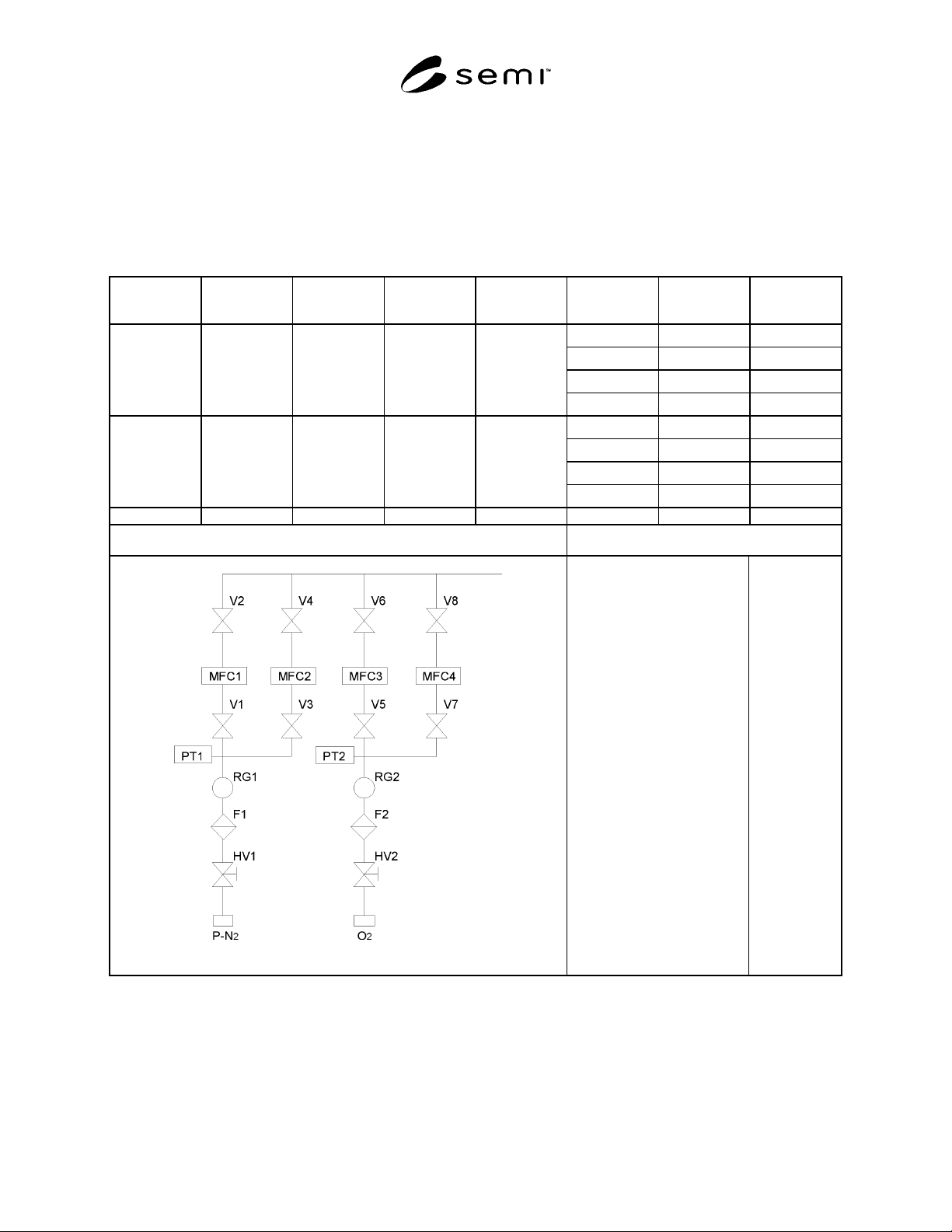
Flow Diagram of System Under Test Test Condition
Counter Type:
Manufacturer of counter
Counter Model
Sample Flow:
Particle Diameter:
Sampler Diameter:
Sample Probe Diameter:
Test gas:
Background Count
Valve Operation Interval:
LPC
A
B
28.3 l/min
≥ 0.1 µ m
30.0 mm
7.53 mm
LN
2
0
30 cycle/
minute
NOTE 1. The test period for O2 line was extended to 76 minutes in order that the total volume of the test flow achieves more than 28.3 liters.

SEMI F70-0302 © SEMI 2002
8
NOTICE: SEMI makes no warranties or representations as to the suitability of the standards set forth herein for any
particular application. The determination of the suitability of the standard is solely the responsibility of the user.
Users are cautioned to refer to manufacturer’s instructions, product labels, product data sheets, and other relevant
literature respecting any materials mentioned herein. These standards are subject to change without notice.
The user’s attention is called to the possibility that compliance with this standard may require use of copyrighted
material or of an invention covered by patent rights. By publication of this standard, SEMI takes no position
respecting the validity of any patent rights or copyrights asserted in connection with any item mentioned in this
standard. Users of this standard are expressly advised that determination of any such patent rights or copyrights, and
the risk of infringement of such rights, are entirely their own responsibility.
Copyright by SEMI® (Semiconductor Equipment and Materials
International), 3081 Zanker Road, San Jose, CA 95134 Reproduction o
f
the contents in whole or in part is forbidden, without express writte
n
content of SEMI.

SEMI F71-1102 © SEMI 2002 1
SEMI F71-1102
TEST METHOD FOR TEMPERATURE CYCLE OF GAS DELIVERY
SYSTEM
This guideline was technically approved by the Global Facilities Committee and is the direct responsibility of
the Japan Facilities Committee. Current edition approved by the Japan Regional Standards Committee on
July 19, 2002. Initially available at www.semi.org September 2002; to be published November 2002.
1 Purpose
1.1 The purpose of this document is to provide a
standardized methodology and procedure for the
leakage performance of gas delivery systems
temperature cycling.
2 Scope
2.1 This test method applies to gas delivery systems
installed in semiconductor manufacturing equipment.
2.2 This standard does not purport to address safety
issues, if any, associated with its use. It is the
responsibility of the users of this standard to establish
appropriate safety health practices and determine the
applicability or regulatory limitations prior to use.
3 Referenced Standards
NOTE 1: As listed or revised, all documents cited shall be the
latest publications of adopted standards.
3.1 SEMI Standards
SEMI F1 — Specification for Leak Integrity of High-
Purity Gas Piping System and Components
4 Terminology
4.1 Definitions
4.1.1 gas delivery system — A system installed in
semiconductor manufacturing equipment to deliver
process and carrier gases to reactors, which typically
consists of tubing, fittings, valves, filters, mass flow
controllers and regulators.
4.1.2 Helium leak test — Testing shall be conducted
per procedure outlined of inboard leak test in SEMI F1.
4.1.3 T-max — The maximum set temperature of the
temperature cycle test.
4.1.4 T-min — The minimum set temperature of the
temperature cycle test.
5 Apparatus
5.1 helium leak detector — The detector has
appropriate detection sensitivity according to SEMI F1.
5.2 constant temperature oven — The constant
temperature oven should have the capacity to
accommodate the test configuration and maintain the
elevated T-max temperature to ± 5° C.
5.3 freezer — The freezer should have the capacity to
accommodate the test configuration and maintain the T-
min temperature to ± 5° C.
5.4 thermocouple — The thermocouple should make
contact with the sample and should take measures of a
noise.
6 Test Specimen and Condition
6.1 The temperature cycling test should be performed
using a typical gas delivery system configuration. An
example is shown in Figure 1.
6.1.1 The influence of heat expansion is not easily
measured with a single component. Therefore, use a
gas panel having a minimum of three lines as an
assembled sample. An example is shown in Figure 1.
6.2 A set temperature (T-max, T-min) at the
temperature cycle must be within the range of the rated
temperature of components used in the gas panel.
6.3 The sealing surface used in the gas delivery system
shall not have any scratches or other defects which are
visible to non-magnified normal vision.
6.4 Install the thermocouple in approximately the
center of the gas panel to be tested.
6.5 The user can arbitrarily decide heating and cooling
temperatures in temperature cycle examination
according to the purpose of use.
6.6 The helium leak test shall be performed only at
room temperature (22 ± 4° C), not during heating or
cooling.
7 Procedure
7.1 A typical gas delivery system configuration is
shown in Figure 1. The following test procedure shall
be interpreted to apply to the actual test target and
deviations from the procedure in this document shall be
recorded along with the test results. (The condition of
heated T-max and cooling T-min was taken up here as
an example.)