semi合集-English.pdf - 第800页
SEMI E110-1102 © SEMI 2001, 2002 2 4.1.4 horizo ntal datum plane — a horizontal plane from which projects the k inematic-cou pling pins on which t he carrier sits. On tool load ports, it is at the load height sp ecified …

SEMI E110-1102 © SEMI 2001, 2002 1
SEMI E110-1102
GUIDELINE FOR INDICATOR PLACEMENT ZONE AND SWITCH
PLACEMENT VOLUME OF LOAD PORT OPERATION INTERFACE FOR
300 mm LOAD PORTS
This guideline was technically approved by the Global Physical Interfaces and Carriers Committee and is the
direct responsibility of the Japanese Physical Interfaces and Carriers Committee. Current edition approved by
the Japanese Regional Standards Committee on July 19, 2002. Initially available at www.semi.org October
2002; to be published November 2002. Originally published November 2001.
1 Purpose
1.1 This guideline defines the zones and volumes in
which load port status indicators and load port
operation switches should be placed. The purpose of
this guideline is to give a similarity in the placement of
them on a 300 mm load port. This guideline only
defines the zones and volumes for them and the exact
placement of them within these zone and volumes are at
the direction of the load port suppliers.
1.2 The zones or volumes may be defined more
precisely by standardization improvement on load port
design and good unification of load port operation
among device manufactures. This guideline may be
improved to be a specification after this effort.
2 Scope
2.1 This guideline defines following recommended
specifications for 300 mm load port.
• Indicator placement zone in which load port status
indicators should be placed.
• Switch placement volume in which load port
operation switch should be placed.
2.2 This guideline covers the specifications for both
fixed buffer equipment and internal buffer equipment.
2.3 This guideline is intended to set an appropriate
level of specification that places minimal limits on
innovation while ensuring modularity and inter-
changeability at all mechanical interfaces. Only the
physical interfaces for the load port are specified; no
materials requirements, micro-contamination limits, use
of or logic associated with the defined physical features
are given in this specification.
2.4 This guideline does not purport to address safety
issues, if any, associated with its use. It is the
responsibility of the users of this guideline to establish
appropriate safety and health practices and determine
the applicability of regulatory limitations prior to use.
3 Referenced Standards
3.1 SEMI Standards
SEMI E15 — Specification for Tool Load Port
SEMI E15.1 — Specification for 300 mm Tool Load
Port
SEMI E47.1 — Provisional Mechanical Specifications
for Boxes and Pods Used to Transport and Store
300mm Wafers
SEMI E57 — Mechanical Specification for Kinematic
Couplings Used to Align and Support 300 mm Wafer
Carriers
SEMI E87 — Specification for Carrier Management
(CMS)
SEMI E101 — Provisional Guide for EFEM Functional
Structure Model
NOTE 1: Unless otherwise indicated, all documents cited
shall be the latest published versions.
4 Terminology
4.1 Definitions
4.1.1 bilateral datum plane — a vertical plane that
bisects the wafers and that is perpendicular to both the
horizontal and facial datum planes (as defined in SEMI
E57).
4.1.2 facial datum plane — a vertical plane that bisects
the wafers and that is parallel to the front side of the
carrier (where wafers are removed or inserted). On tool
load ports, it is also parallel to the load face plane
specified in SEMI E15 on the side of the tool where the
carrier is loaded and unloaded (as defined in SEMI
E57).
4.1.3 fixed buffer equipment — production equipment
that has only fixed load ports and no internal buffer for
carrier storage. Substrates are loaded and unloaded
directly from the carrier at the load port for processing
(as defined in SEMI E87).
SEMI E110-1102 © SEMI 2001, 2002 2
4.1.4 horizontal datum plane — a horizontal plane from which projects the kinematic-coupling pins on which the
carrier sits. On tool load ports, it is at the load height specified in SEMI E15 and might not be physically realized as
a surface (as defined in SEMI E57).
4.1.5 indicator placement zone — a zone in which load port status indicators are placed.
4.1.6 internal buffer equipment — equipment that uses an internal buffer (as defined in SEMI E87).
4.1.7 load port operation interface — any indicator (e.g. lamp, LED) to visualize status information of a load port
to an operator and/or any switch to be used for manual handoff operation.
4.1.8 load port operation switch — any switch to be used for manual handoff operation.
4.1.9 load port status indicator — any indicator (e.g. lamp, LED) to visualize status information of a load port to an
operator.
4.1.10 switch placement volume — a volume in which load port operation switch is placed.
5 Requirements
5.1 Indicator placement zone
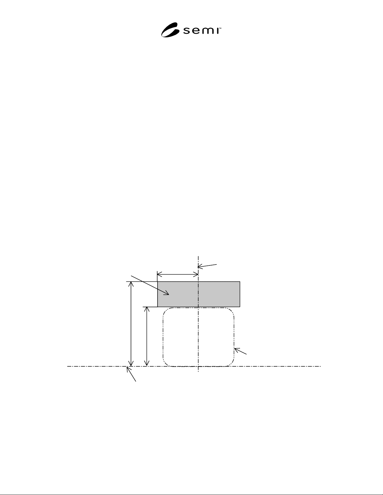
5.1.1 Indicator Placement Zone for a Load Port per SEMI E15.1 Option 1 — It is recommended that load port
status indicators should be positioned within a zone given by x400, z400, and z401. The exact placement of them
within this zone is at the direction of the load port supplier. They may be located at or behind (away from the
operator) the equipment boundary. Clearances required by SEMI E15.1 cannot be violated.
NOTE 2: The indicator placement zone is not an exclusion zone. No assumption can be made that this zone needs to be kept
empty by the load port supplier. Furthermore, no assumption can be made that a load port must have a physical surface
representing the indicator placement zone.
x400=237.5
z401=486
z400=340
Horizontal Datum Plane
C
L
Bilateral Datum Plane
Indicator placement zone
Approximate FOUP envelope
Figure 1
Indicator Placement Zone for a Load Port Per SEMI E15.1 Option 1
SEMI E110-1102 © SEMI 2001, 2002 3
Table 1 Dimensions of indicator placement zone for a load port per SEMI E15.1 Option1
Symbol Used Figure Value Specified Reference Measured From
x400 1 237.5 mm (9.35 in.) bilateral datum plane
z400 1
340 mm (13.39 in.)
horizontal datum plane
z401 1 486 mm (19.13 in.) horizontal datum plane
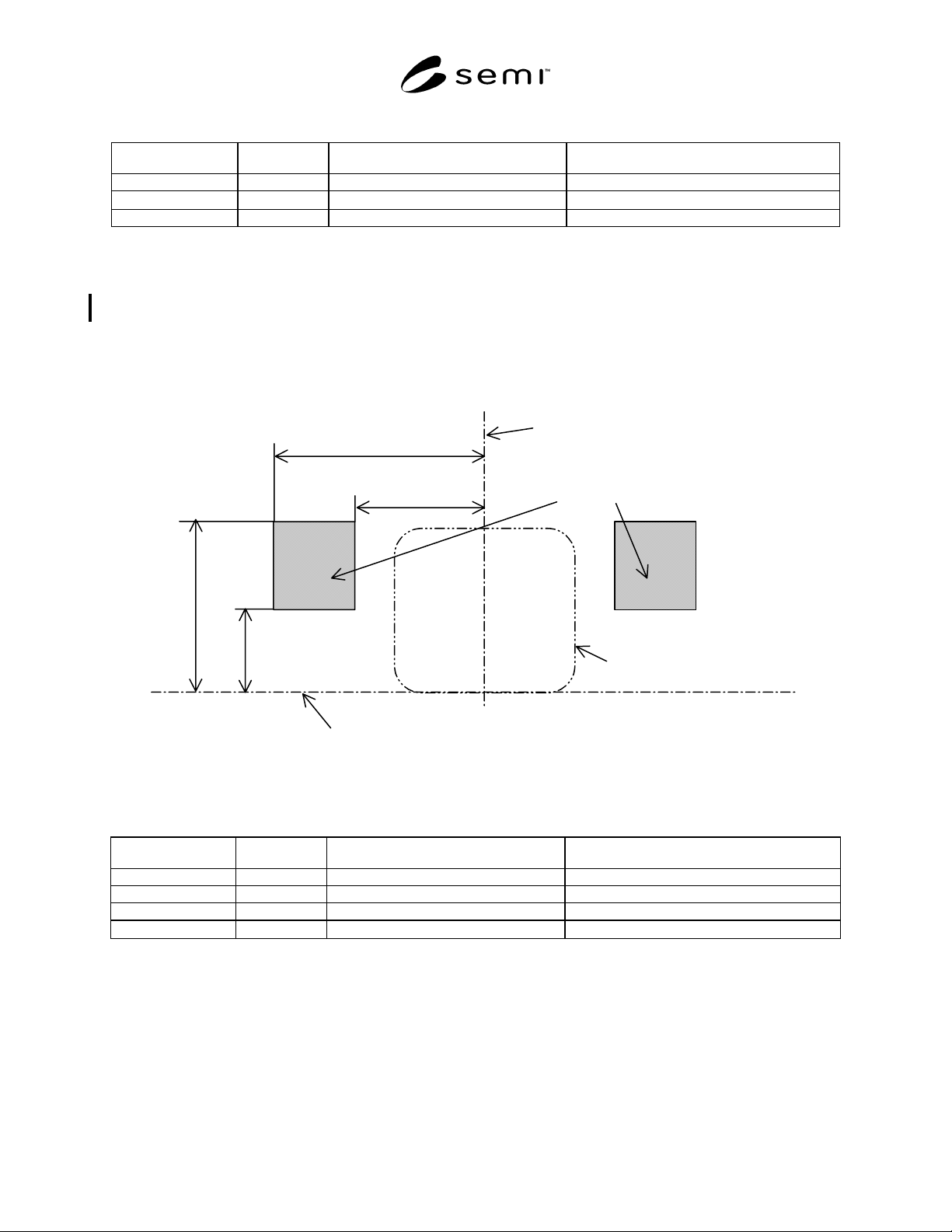
5.1.2 Indicator placement zone for a load port per SEMI E15.1 Option 3 — It is recommended that load port status
indicators should be positioned within a zone given by x401, x402, z402 and z403. The exact placement of them
within this zone is at the direction of the load port supplier. They may be located at or behind (away from the
operator) the load face plane. Clearances required by SEMI E15.1 cannot be violated.
NOTE 3: The indicator placement zone is not an exclusion zone. No assumption can be made that this zone needs to be kept
empty by the load port supplier. Furthermore, no assumption can be made that a load port must have a physical surface
representing the indicator placement zone.
x402=475
x401=290
z403=390
z402=190
Horizontal Datum Plane
C
L
Bilateral Datum Plane
Indicator placement zone
Approximate FOUP envelope
Figure 2
Indicator Placement Zone for a Load Port Per SEMI E15.1 Option 3
Table 2 Dimensions of indicator placement zone for a load port per SEMI E15.1 Option3
Symbol Used Figure Value Specified Reference Measured From
x401 2 290 mm (11.42 in.) bilateral datum plane
x402 2 475 mm (18.79 in.) bilateral datum plane
z402 2 190 mm (7.48 in.) horizontal datum plane
z403 2
390 mm (15.35 in.)
horizontal datum plane
5.2 Switch Placement Volume — For a load port according to option 1 and 3 per SEMI E15.1, it is recommended
that load port operation switches should be positioned in a way, that the surface of the switch is within a volume
given by x403, x404, r400, y402 (equal to the maximum values of r67 and y53
defined in SEMI E47.1 respectively),
y400, y401 (equal to the maximum value of D defined in SEMI E15.1), z404, and z405. The exact placement of the
switches within this volume is at the discretion of the load port supplier.
NOTE 4: The switch placement volume is not an exclusion volume. No assumption can be made that this volume needs to be
kept empty by the load port supplier. Furthermore, no assumption can be made that a load port must have a physical surface
representing the switch placement volume.