semi合集-English.pdf - 第6350页
7 SEMI G69-0996 © SEMI 1996, 2004 12 Calculation 12.1 Shear and Pull Method 12.1.1 The adhesive strength is calculated as fo llows: 12.1.1.1 Adhesive Stre ngth (N/m m 2 ) = Peak Load (N)/Nominal Adhesive Area (mm 2 ) 12.…
SEMI G69-0996 © SEMI 1996, 2004 6
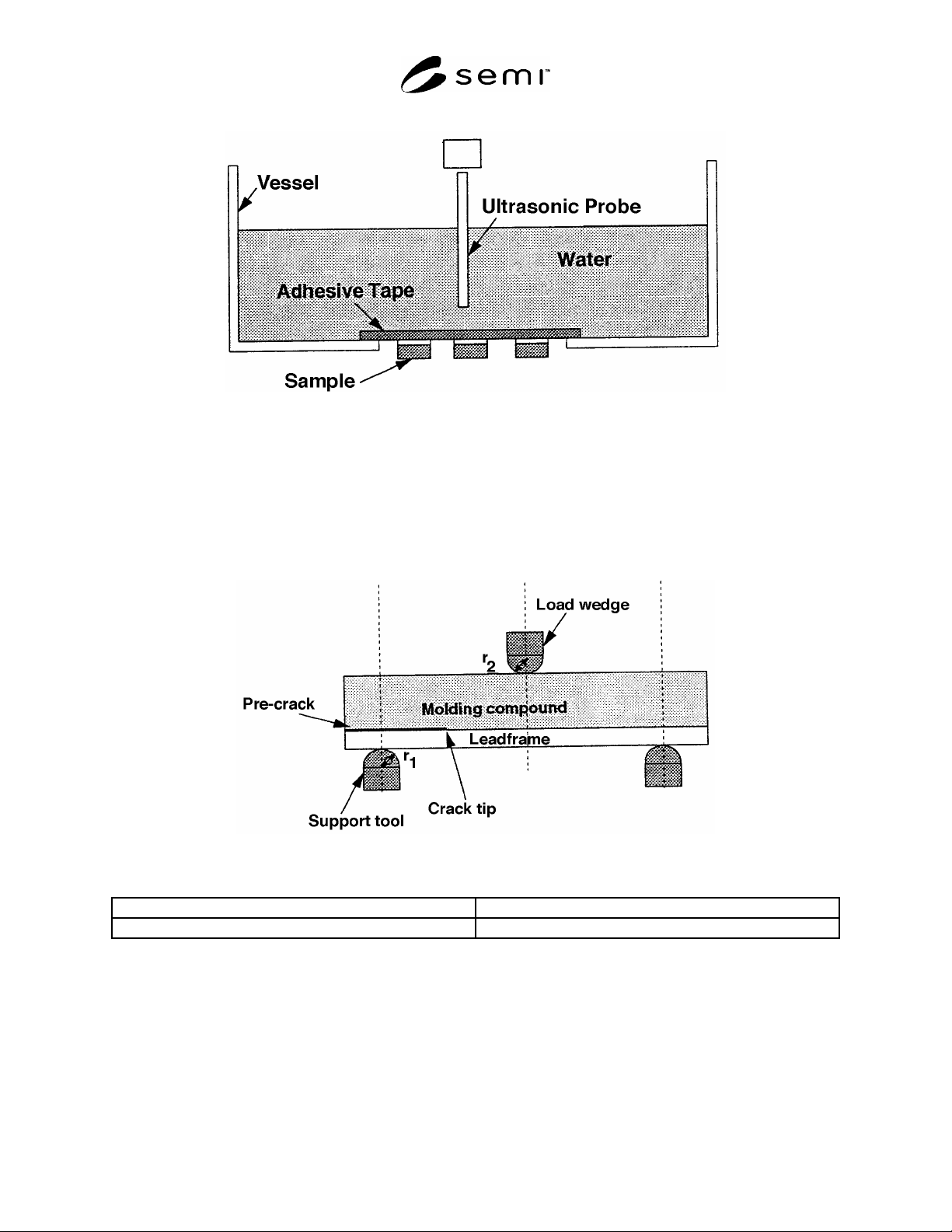
Figure 4
Measurement of Pre-Crack Length
11.3.2 Test Procedure
11.3.2.1 Attach support fixture and load wedge to the tensile tester.
11.3.2.2 Place the sample on the support fixture with the molded side up (see Figure 5).
NOTE 8: The support fixture tool should be located at a constant distance from the tip of pre-crack for every measurement.
Figure 5
Sample Setup
Radius of support tool r
1
5–8 mm
Radius of load wedge r
2
2–5 mm
11.3.2.3 Place the load wedge in contact with the molded surface and initiate the loading at a constant speed
between 2–10 mm/min while recording the load and displacement.
11.3.2.4 Record the peak load before the sudden drop in applied load.
11.3.2.5 Repeat the test with another sample which has the leadframe side up.
7 SEMI G69-0996 © SEMI 1996, 2004
12 Calculation
12.1 Shear and Pull Method
12.1.1 The adhesive strength is calculated as follows:
12.1.1.1 Adhesive Strength (N/mm
2
) = Peak Load (N)/Nominal Adhesive Area (mm
2
)
12.2 Three-Point Bending Method
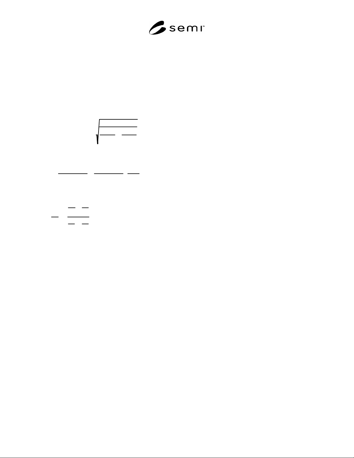
12.2.1 Apparent Adhesive Strength — Apparent adhesive strength including residual stress, is calculated using the
stress intensity factor K
i
as follows:
K
i
4 10
6
cosh(
)
G
p
1
p
a
1
a
where
G=3
1
t
p
3
p
t
p
3
a
t
p
p
t
a
a
k
P
2
a
2
2b
2
k=4t
p
t
a
p
a
t
p
t
a
2
t
p
2
p
t
a
2
a
2
1
2
ln
p
p
1
a
a
a
1
p
j
3 4
j
(j = p or a)
P : Peak load (N)
a : Pre - crack length (m)
b : Sample width (m)
t
p
: Thickness of molding compound (m)
t
a
: Thickness of leadframe (m)
p
: Young' s modulus of molding compound (Pa)
a
: Young' s modulus of leadframe (Pa)
p
: Shear modulus of molding compound (Pa)
a
: Shear modulus of leadframe (Pa)
p
: Poisson' s ratio of molding compound
a
: Poisson' s ratio of leadframe

SEMI G69-0996 © SEMI 1996, 2004 8
12.2.2 True Adhesive Strength — The true adhesive strength (CKic) excluding residual stress, is calculated as
follows:
K
ic
MPa m
K
ib1
K
ib2
2
where :
K
ib1
: Apparent adhesive strength when testing is performed with molded side up (MPa m
)
K
ib2
: Apparent adhesive strength when testing is performed with leadframe side up (MPa m
)
13 Report
13.1 The following items should be reported:
13.1.1 Leadframe
13.1.1.1 Material Designation
13.1.1.2 Thickness
13.1.1.3 Production Method (etching or stamping)
13.2 Pre-Treatment — In case that surface pre-treatment is necessary, the process and their condition should be
reported as follows:
13.2.1 Pre-treatment by plating
13.2.1.1 Plating type
13.2.1.2 Plating thickness
13.2.2 Post treatment after plating
13.2.2.1 Corrosion prevention treatment
13.2.2.2 Cleaning treatment
13.2.2.3 Coupling material
13.2.3 Pre-treatment by heating
13.2.3.1 Temperature
13.2.3.2 Atmosphere
13.2.3.3 Oven or Hot Plate
13.3 Molding Compound
13.3.1 Material Designation
13.4 Molding Compound Configuration and Dimension
13.5 Molding Condition
13.5.1 Pre-heat condition (Temperature, Time)
13.5.2 Molding condition (Cure temperature, Cure time, Injection speed, Injection pressure)
13.5.3 Post-cure condition (Temperature, Time)
13.5.4 Sample storage conditions
13.6 Measurement Method (Shear, Pull, or Three-point bending method)
13.7 Measurement Equipment