semi合集-English.pdf - 第1490页
SEMI E30.5-0302 © SEMI 2001, 2002 18 12 Remote Commands 12.1 T he purpose of this section is to identify the MSEM required rem ote co m mands, command par ameter s, and valid c omma nds ve rsu s MSEM state s. 12.2 Requir…
SEMI E30.5-0302 © SEMI 2001, 200217
11.2.7.1 There are five types of DEF-LIST tables:
• SITE-DEF-LIST: A list of Sites and their attributes, typically the list of sites to be measured.
• ALIGN-DEF-LIST: A list of alignment sites and their attributes.
• M21-ELEMENT-DEF-LIST: A list of element ID and their low left hand location in M20P or SEMI M20
coordinates.
• M21-ELEMENT-SITE-DEF-LIST: A list of ElementID's and what sites are to be measured within that element.
• M21-ELEMENT-ALIGN-DEF-LIST: a list of ElementID's and the alignment sites to be used at each.
NOTE 2: The attributes are equipment-defined.
11.2.7.2 To support the SiteList, and AlignList, for SEMI M20, M20P and SEMI M21, the following types of tables
must be implemented: SITE-DEF-LIST, ALIGN-DEF-LIST, or M21-ELEMENT-SITE- DEF-LIST, M21-
ELEMENT-ALIGN-DEF-LIST and M21-ELEMENT-DEF-LIST. A host would send a DEF-LIST to equipment
using standard transfer methods for tables as defined by ARAMS (SEMI E58). MSEM requires that the following
columns be included in the DEF-LIST tables. The DEF-LIST-TABLE components table defines the DEF-LIST
column names and their allowable format is given below.
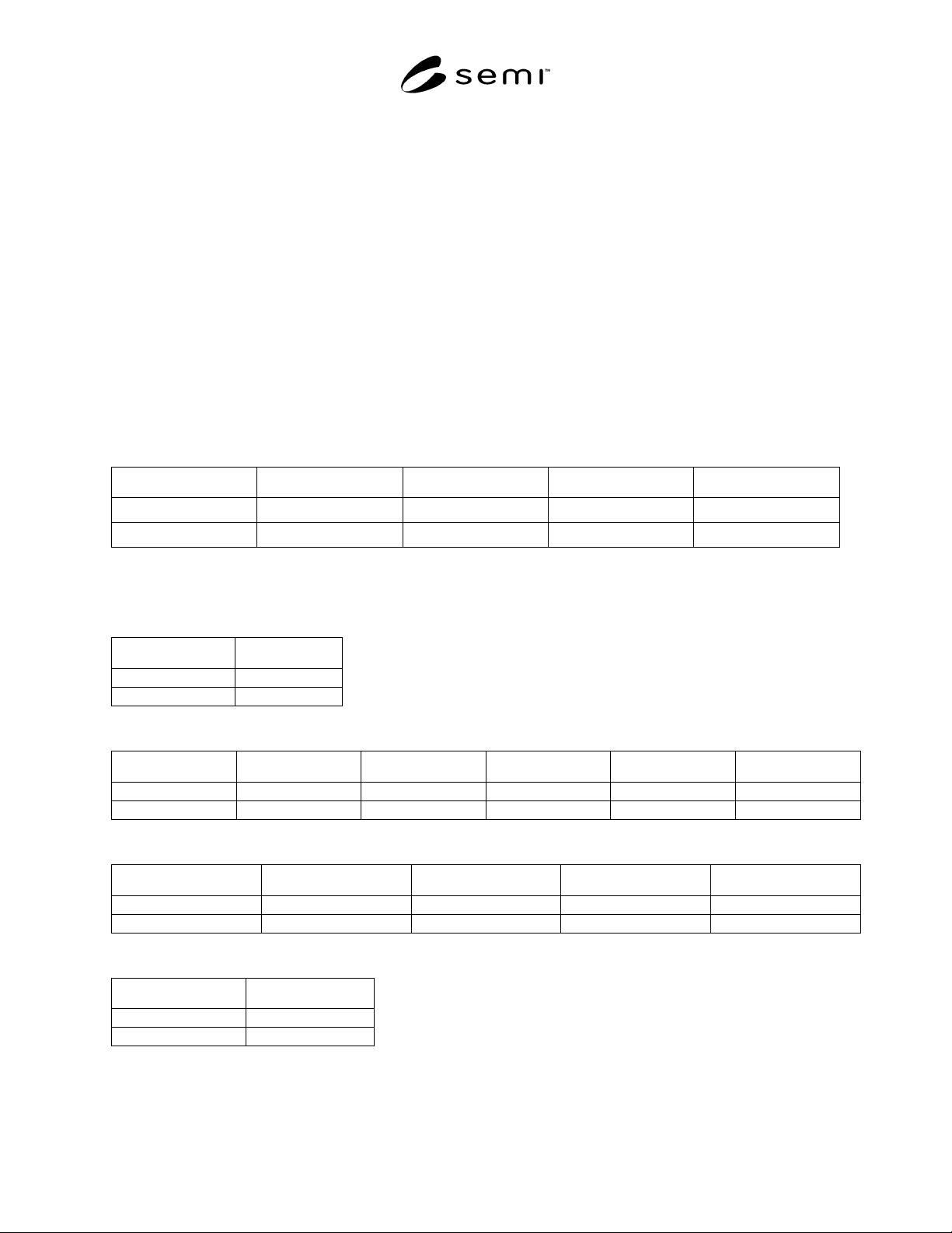
Table 7 SITE-DEF-LIST
Sitename Coordx Coordy Coordsys Site- Attribute(n)
11.2.7.3 For SEMI M21 Coordinate system an additional table is required.
Table 8 M21-ELEMENT-SITE-DEF-LIST
Element id Sitename
Table 9 M21-ELEMENT-DEF-LIST
Element id Coordx Coordy Coordsys m21xsize m21ysize
Table 10 ALIGN-DEF-LIST
Align-Name Coordx Coordy Coordsys Align- Attribute(n)
Table 11 M21-ELEMENT-ALIGN-DEF-LIST
Element id Align-Name

SEMI E30.5-0302 © SEMI 2001, 2002 18
12 Remote Commands
12.1 The purpose of this section is to identify the
MSEM required remote commands, command
parameters, and valid commands versus MSEM states.
12.2 Requirements
The following capabilities are
required:
• StartProcessing
• Stop Processing
• Temporaly Suspend Processing
• Resume Processing
• Abort Processing
• Select Process Programs, Material and/or Sites to
Measure
• Report Location of Material Found within a
cassette
12.3 All the remote commands defined by MSEM are
required unless they have been qualified by the
statement “if the equipment supports this functionality
it shall use this command”. Then, they are only required
if the equipment supports the functionality necessary to
support the command. A good example of this is the
MAP-CASSETTE command if the equipment does not
have the hardware necessary to scan a cassette for the
presence of substrates in slots then the command is not
required by the MSEM. The alphanumeric strings
defined by MSEM for RCMD and CPNAME are
required.
12.4 Definitions
12.4.1 Host Command Parameter (CPNAME/CPVAL)
— a parameter name/value associated with a particular
host command (S2,F49). This document will specify
unique names (CPNAMEs) and values (CPVALs) for
many command parameters. Note that if there are no
associated parameters a zero-length list is sent.
12.5 Remote Commands Description — this section
describes required functionality, suppliers may
implement additional commands. The following remote
commands (RCMDs) must be supported as described
below.
NOTE 2: The terms “current cycle” and “safe point” used
below are to be defined by the supplier.
12.5.1 ABORT terminate the current cycle prior to
its completion. Abort has the intent of immediately
stopping the process and is used because of abnormal
conditions. Abort makes no guarantee about the
subsequent condition of material except as noted in the
CPNAME ABORT-LEVEL description.
12.5.2 CLEANUP
Process Program deselection,
removal of all material to output locations and any
equipment specific activities needed to transition into
the IDLE state. Completion of this command should
generate a collection event report.
12.5.3 NEXT-MATERIAL
processing of the current
substrate is halted at the first safe point and unloaded to
the target cassette location. Next-material has the intent
of allowing the host to skip measurement of the current
substrate. This is a trigger for processing state
transition from WORKING to UNLOAD.
12.5.4 PAUSE
suspend processing temporarily at
the next safe point. Pause has the intent of resuming
the process at the same point where it was paused.
RESUME or PP-UPDATE may be used to resume the
process.
12.5.5 PP-ASSIGN
instructs the equipment to assign
a process to a carrier ID(s)/location(s) and place the
exchange station in the process queue with the given
priority. Only one assignment is allowed for a exchange
station. Without specifying a priority, the material is
queued with the default priority. Material with equal
priority are queued in the order the PP-ASSIGN
commands are received. If the equipment supports the
functionality of queuing material, it will use this
command.
12.5.6 PP-SELECT
instructs the equipment to make
the requested Process Program(s) available in the
execution area. Additionally, to reduce the number of
Process Programs on the equipment, PP-SELECT may
define the material to be measured, measurement site
locations, and/or the information needed for site
alignment; default values shall be used if this
information is not specified. This is a trigger for the
processing state transition from IDLE to SETTING UP.
All Process Programs specified in the command are to
be validated
12.5.7 PP-UPDATE
provides the ability to alter
Process Program variables during the PAUSED
processing state. Any CPNAMEs specified in PP-
UPDATE will replace the previous definitions. This
command will RESUME the process. If the PP-
UPDATE fails, the Process Program variables present
prior to the PP-UPDATE are retained. If no parameters
values are specified, the defaults are used.
12.5.8 RESUME
resume processing from the point
where the process was paused. This is the trigger for
processing state transition 10, from PROCESS PAUSE.
12.5.9 START
instructs the equipment to initiate
processing. This is the trigger for the processing state
transition from READY to LOAD.

SEMI E30.5-0302 © SEMI 2001, 200219
12.5.10 STOP
complete the current cycle, stop in a safe condition and return to the IDLE processing state. Stop
has the intent of stopping the process entirely. The equipment is not required to support the continuation of
processing.
12.6 Host Command Parameters Names (CPNAME)
Table 12 Host Command Parameter Table
CPNAME
CPVAL
Description Range Format
CARRIERBLD L,2
1. L,2
1. CP-CARRIERID **
2. CARRIERID
or
1. L,2
1. CP- LOCATIONID **
2. (STORAGE)ID
2. L,N
1. L,2
1. PROCESS-BLD-GROUP
2. L,M
:
N. L,2
1. PROCESS-BLD-GROUP
** Both CP-CARRIERID and CP-LOCATION may be
included if no carrier ID reader is available.
CP-ABORT-LEVEL MSEM defined abort levels
HALT - halt,
goto ABORTED
CLEANUP - halt, preform cleanup procedure,
goto ABORTED
“HALT”
“CLEANUP”
A[7]
CP-ALIGNLIST L,n
1. CP-ALIGNNAME
:
n.
For the SEMI M20 or M20P Coordinate system
CP-ALIGN-DEF-LIST As defined in Section 9
CP-ALIGNNAME Alignment name A[1..80]
CP-AUTOSTART Defines if a START command is required from an
external source (operator or host) to exit the READY
state. 0 = START command required,
1 = AUTOSTART no external START command
required to begin execution.
0–1 U1
CP-CARRIERID ID of carrier that the measurement data is associated
with.
A[1..16]
CP-ELEMENTID The M21 address for a specific rectangular pattern on
the wafer.
I4[2]