semi合集-English.pdf - 第6014页
SEMI G1-96 © SEMI 1 980, 199 6 7 9.4.6.2 Voids or Pits — Expos ure of b a s e metal with any dim ension great er than 0.001 " (0.025 mm ). 9.4.6.3 D iscoloration, Bl istering, or P e e ling of the Metallization 9.4.…
SEMI G1-96 © SEMI 1980, 1996 6
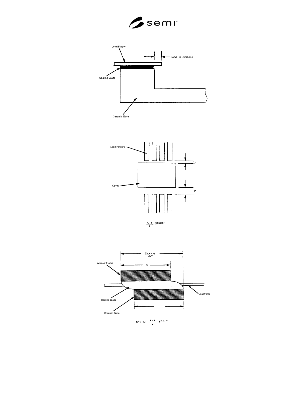
Figure 5
9.4.5.2 Lead Misalignment to Ceramic Base — 0.010" (0.254 mm) maximum (see Figure 6).
Figure 6
9.4.5.3 Window Assembly Misalignment — 0.015" (0.358 mm) maximum (see Figure 7).
Figure 7
9.4.6 Die-Attach Pad (Leadframe)
9.4.6.1 Flatness across the pad and parallelism to the base and window shall be agreed upon between user and
supplier.

SEMI G1-96 © SEMI 1980, 19967
9.4.6.2 Voids or Pits — Exposure of base metal with
any dimension greater than 0.001" (0.025 mm).
9.4.6.3 Discoloration, Blistering, or Peeling of the
Metallization
9.4.6.4 Scratches or Scrapes — Any b uild-up of
metallization or exposure of base metal.
9.4.6.5 Foreign Material, Including Glass Splatter or
Projections — No more than three sites, each with a
maximum dimension in any plane of 0.001" (0.025
mm).
9.4.7 Mechanical Damage — Leads
9.4.7.1 Broken, Kinked, or Missing Leads
9.4.7.2 Twist — Any lead twisted by more than 10°
from the untwisted condition.
9.4.7.3 Bottom-Formed Width — Any sub-assembly
with the bottom-formed width of the leadframe
exceeding ± 0.010" (0.254 mm).
9.4.7.4 Top-Formed Width — Any sub-assembly with
the top-formed width of the leadframe exceeding ±
0.010" (0.254 mm).
10 Incoming Inspection and Functional Tests
10.1 Incoming Inspection
10.1.1 Dimensional Inspection per Section 7.
10.1.2 Visual inspection per Section 9 at 10×
magnification with vertical lighting.
10.1.3 Metallization
10.1.3.1 Die-Attach Metallization — Thickness shall
be measured by standard cross-sectioning without
smearing or by X-ray fluorescence.
10.1.3.2 Lead Bond Metallization — Thickness shall
be measured by X-ray fluorescence.
10.1.3.3 External Lead Plating (If Applicable) —
Thickness shall be measured by X-ray fluorescence.
10.1.4 Lead Solderability (If Applicable) — Tested in
accordance with MIL-STD-883, Method 2003.
10.2 Functional Testing
NOTE 9: All procedures to functionally test the components
or sub-assemblies shall be agreed upon between user and
supplier.
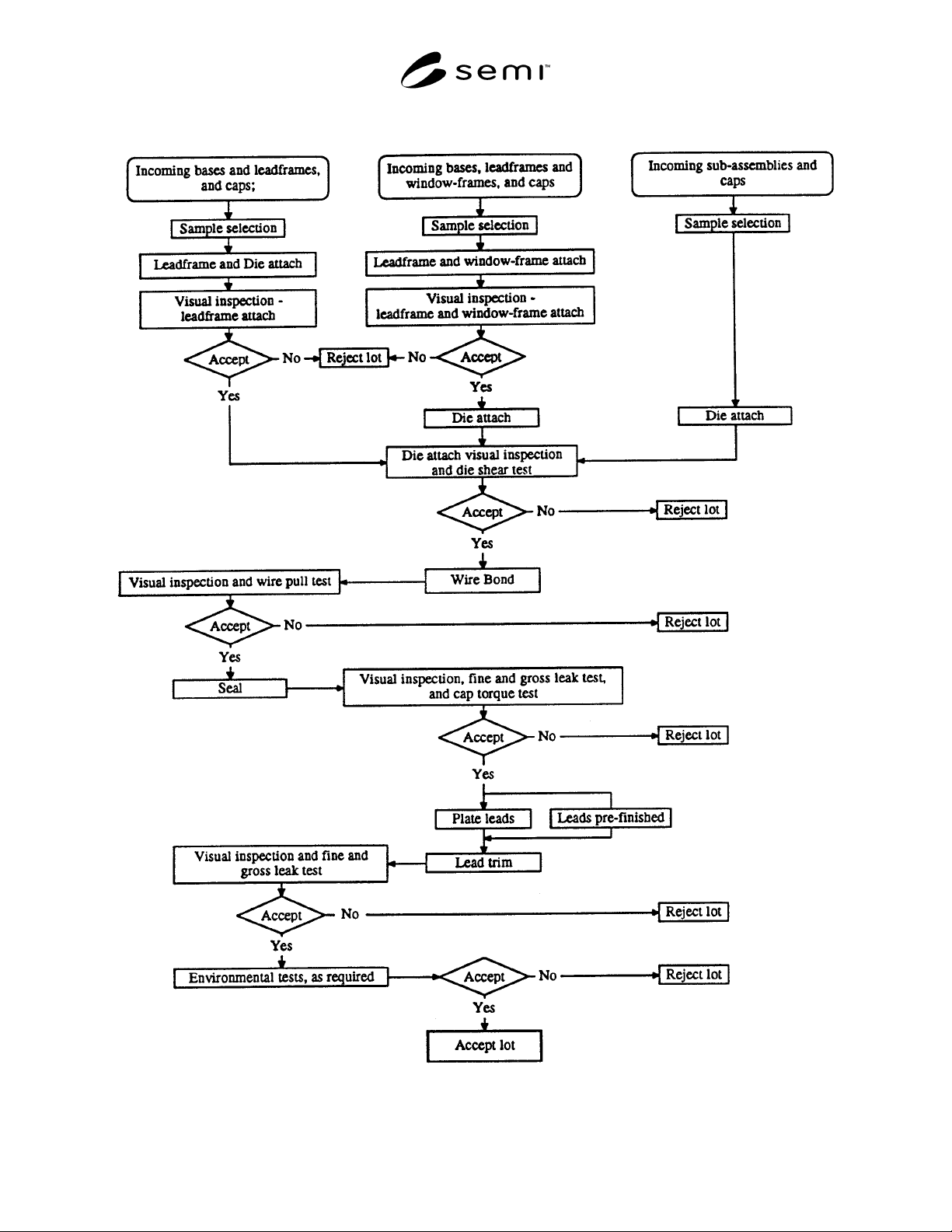
The sequence of functional testing (and subsequent
environmental testing) shall be as shown in Figure 8.
SEMI G1-96 © SEMI 1980, 1996 8
Figure 8