semi合集-English.pdf - 第4402页
SEMI F97-0305 © SEMI 2005 12 Table 4 State Transition Table Run- Mode Number Previous State Trigge r New State Actions Remark 1 (no state) Start up of FPU. Down or Stand by or Run None. Dependent on type of FPU; Normally…
SEMI F97-0305 © SEMI 2005 11
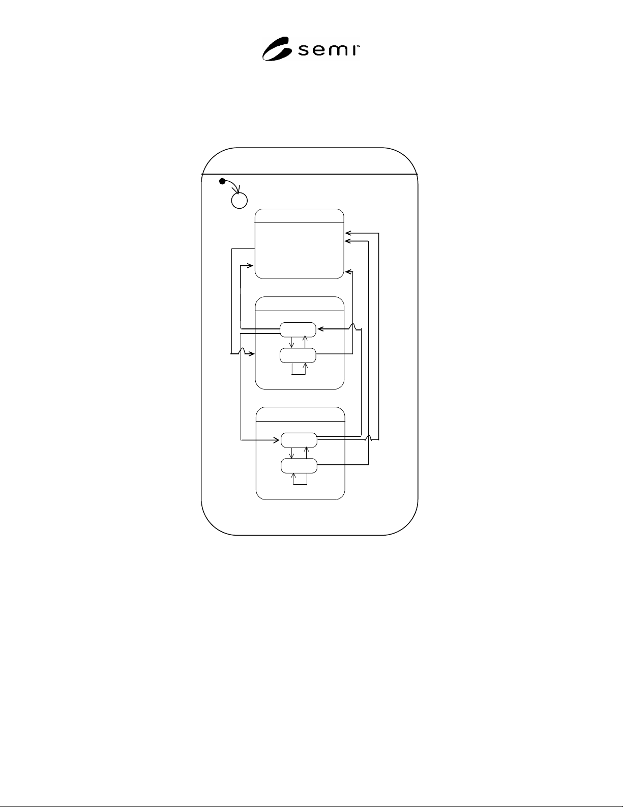
9.4.5.3 The locked sub state of Run and Stand-by may be used in order to force the FPU to maintain the current Run
or Stand-by state until the lock is disabled. The reasons causing the lock are out of scope of this standard. In
addition to the trigger to unlock, only critical failures can cause the FPU to leave the locked sub state. These critical
failures are being defined on a case by case basis by the purchaser and supplier of the FPU and the system
integrator.
Run-Mode
C
1
Run
Not_locked
Locked
10
12
11
14
Down
Stand-by
Not_locked
Locked
4
6
5
8
3
2
13
9
7
Figure 7
State Transition Diagram Run-Mode
SEMI F97-0305 © SEMI 2005 12
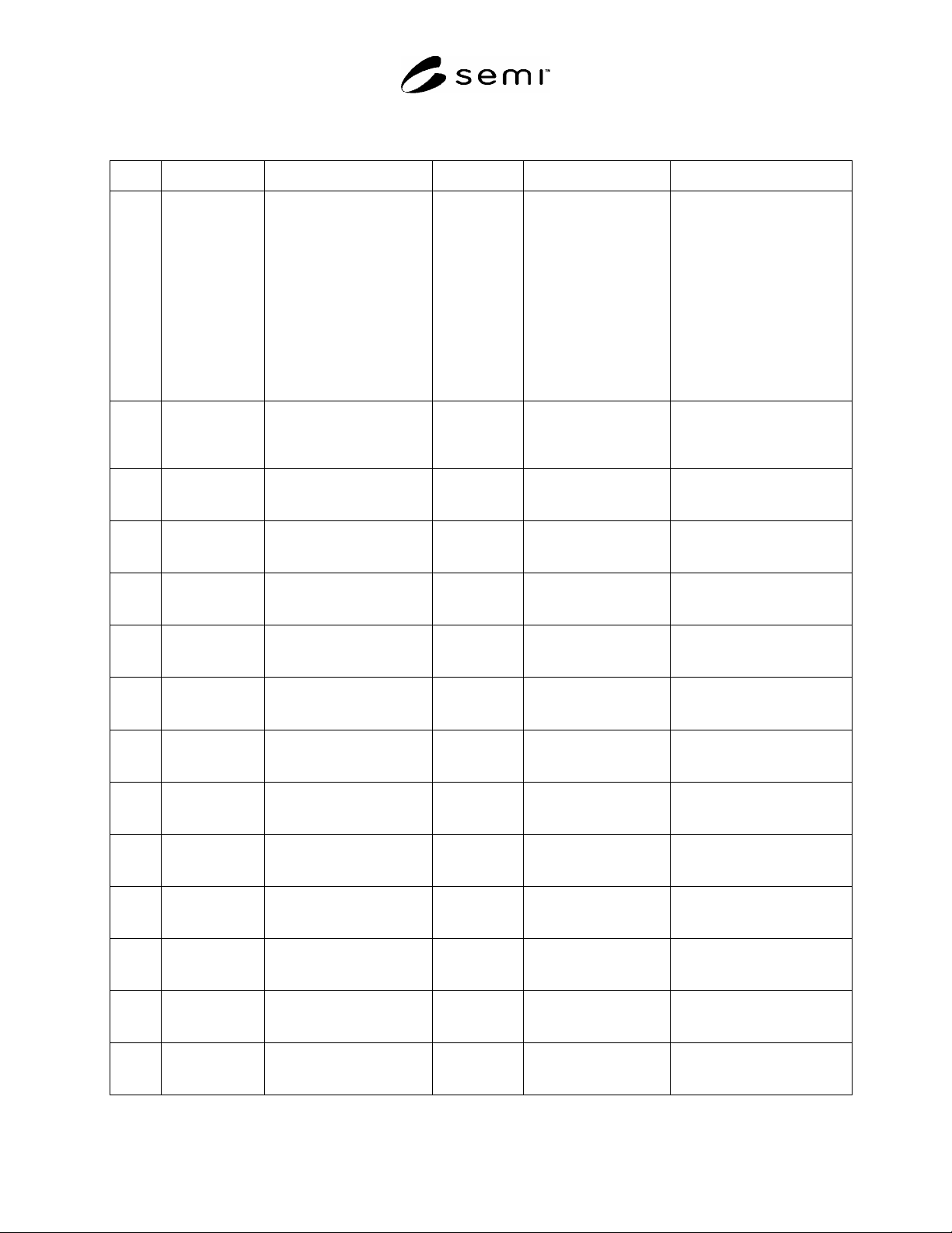
Table 4 State Transition Table Run-Mode
Number Previous State Trigger New State Actions Remark
1 (no state) Start up of FPU. Down
or
Stand by
or
Run
None. Dependent on type of FPU;
Normally when to Stand-by
then to Stand by and not
locked, but an automatic
function may force FPU to
Stand-by and locked;
Normally when to Run then to
Run and not locked, but an
automatic function may force
FPU to Run and locked.
2 Down Trigger to activate the
principal availability of the
FPU (e.g. operator action or
logical function).
Stand-by FPU activates its stand-
by functions including
watchdog-toggle.
Normally to Stand-by and not
locked, but an automatic
function may force FPU to
Stand-by and locked.
3 Stand-by
and
Not_Locked
Failure occurred. Down FPU deactivates its
stand-by functions.
4 Stand by
and
Not_Locked
Trigger to lock Stand by
state.
Stand-by and
Locked
FPU ignores trigger and
any request to change
state of Run-mode.
5 Stand-by
and
Locked
Trigger to perform a
scheduled down or non
critical failure.
Stand-by and
Locked
FPU ignores trigger and
any request to change
state of Run-mode.
6 Stand-by
and
Locked
Trigger to unlock. Stand by and
Not_Locked
FPU releases pending
triggers to change to
other states.
7 Stand-by
and
Locked
Critical failure occurred. Down FPU deactivates its stand
by functions.
8 Stand-by
and
Not_Locked
Trigger to activate Run (e.g.
operator action or logical
function).
Run
and
Not_Locked
FPU activates its running
functions.
9 Run
and
Not_Locked
Trigger to activate Stand-by
(e.g. operator action or
logical function).
Stand-by
and
Not_Locked
FPU deactivates its
running functions.
10 Run
and
Not_Locked
Trigger to lock Run. Run
and
Locked
FPU ignores trigger and
any request to change
state of Run-mode.
11 Run
and
Locked
Trigger to perform a
scheduled down or non
critical failure.
Run
and
Locked
FPU ignores trigger and
any request to change
state of Run-mode.
12 Run
and
Locked
Trigger to release locked
state of Run.
Run
and
Not_Locked
FPU releases pending
triggers to change to
other states.
13 Run
and
Locked
Critical failure occurred. Down FPU stops its running
functions.
14 Run
and
Not_Locked
Trigger to perform a
scheduled down or a critical
failure.
Down FPU deactivates its
running functions.
SEMI F97-0305 © SEMI 2005 13
9.4.6 Alarm-Mode
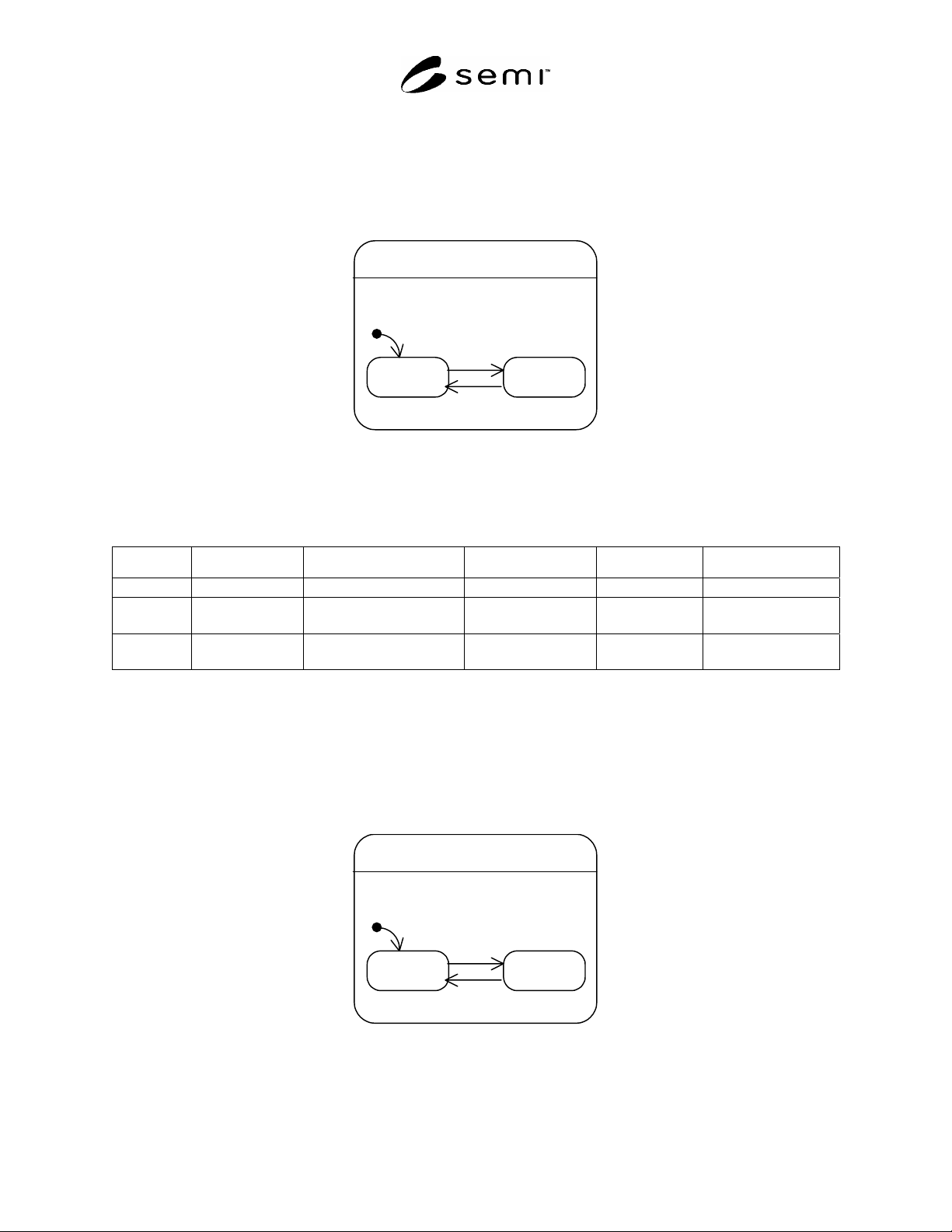
9.4.6.1 Alarms are being defined on a case by case basis between the purchaser and the supplier of the FMCS and
FPUs and the system integrator. Alarm-Mode specifies whether an alarm occurred:
No_Alarm: No alarm present.
Alarm: An alarm is present (at least one part of the FPU is in alarm condition
).
Alarm-Mode
No_Alarm Alarm
2
3
1
Figure 8
State Transition Diagram Alarm-Mode
Table 5 State Transition Table Alarm-Mode
Number Previous State Trigger New State Actions Remark
1 (no state) Start up of FPU. No_Alarm None.
2 No_Alarm Alarm event occurred. Alarm FPU may perform
alarm routines.
3 Alarm Alarm condition
disappeared.
No_Alarm FPU releases
alarm routines.
9.4.7 Warning-Mode
9.4.7.1 Warnings are being defined on a case by case basis between the purchaser and supplier of the FMCS and
FPUs and the system integrator. Warning-Mode specifies whether a warning occurred:
No_Warning: No warning present
Warning: Warning present.
Warning-Mode
No_Warning Warning
2
3
1
Figure 9
State Transition Diagram Warning-Mode