semi合集-English.pdf - 第2300页
SEMI E81-0600 © 1999, 2 000 37 Ba nk Cus t om er : B AT M : A 1: reques t Ses s ion( ) 2: request I dent if i c ati on( ) 3: pr ovi deI dent if icat i on( idNum b er) 4: v erif y I dent if icat ion( ) Figure 24 Component…
SEMI E81-0600 © 1999, 2000 36
B
<<In te r fa c e >>
C
<<Interface>>
A
<<Interface>>
Association Class
D
<<Interface >>
2
0..1
2
0..1
Association Nam e
F
<<Interface>>
E
<<Interface >>
1..*
1
1..*
1
Association Name
G
<<Interface>>
Zero or
One
Subtype
Relationship
Part-Whole
Relationshop
Data-
Carrying
RelationshipExactly
Two
One
One or
Many
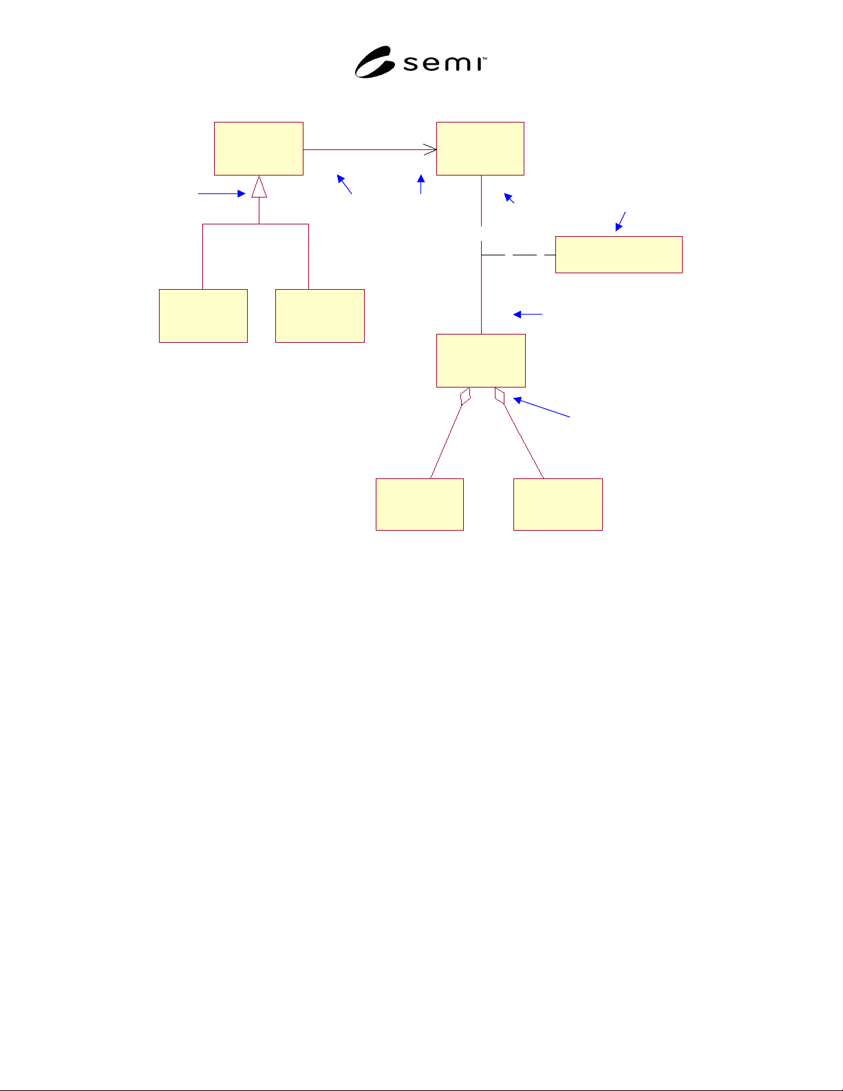
Figure 23
Information Model Example
7.4.3.4 Component Interaction Model
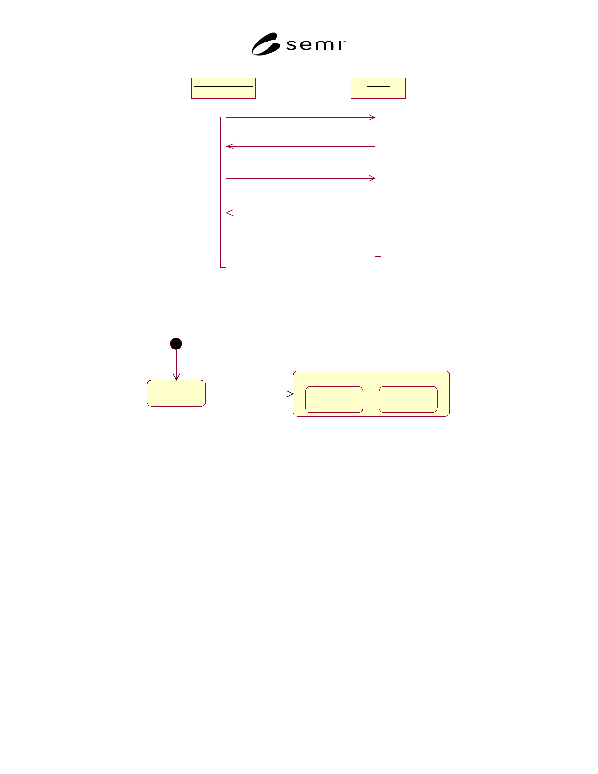
7.4.3.4.1 The Component Interaction Model expresses
framework dynamics by describing the sequence of
collaborations between objects supporting CIM
Framework interfaces. This model is represented using
the UML Sequence Diagram [UML]. The vertical lines
each represent an object that conforms to a role
specified by a CIM Framework interface. This is called
a “lifeline.” The connecting arrows represent messages
that flow between these objects and the data they
convey. Each message must map to a defined operation
on the interface of the message recipient. The example
shown in Figure 24 of a Sequence Diagram models a
portion of the interaction between a bank customer and
an Automated Teller Machine (ATM).
7.4.3.5 State Model
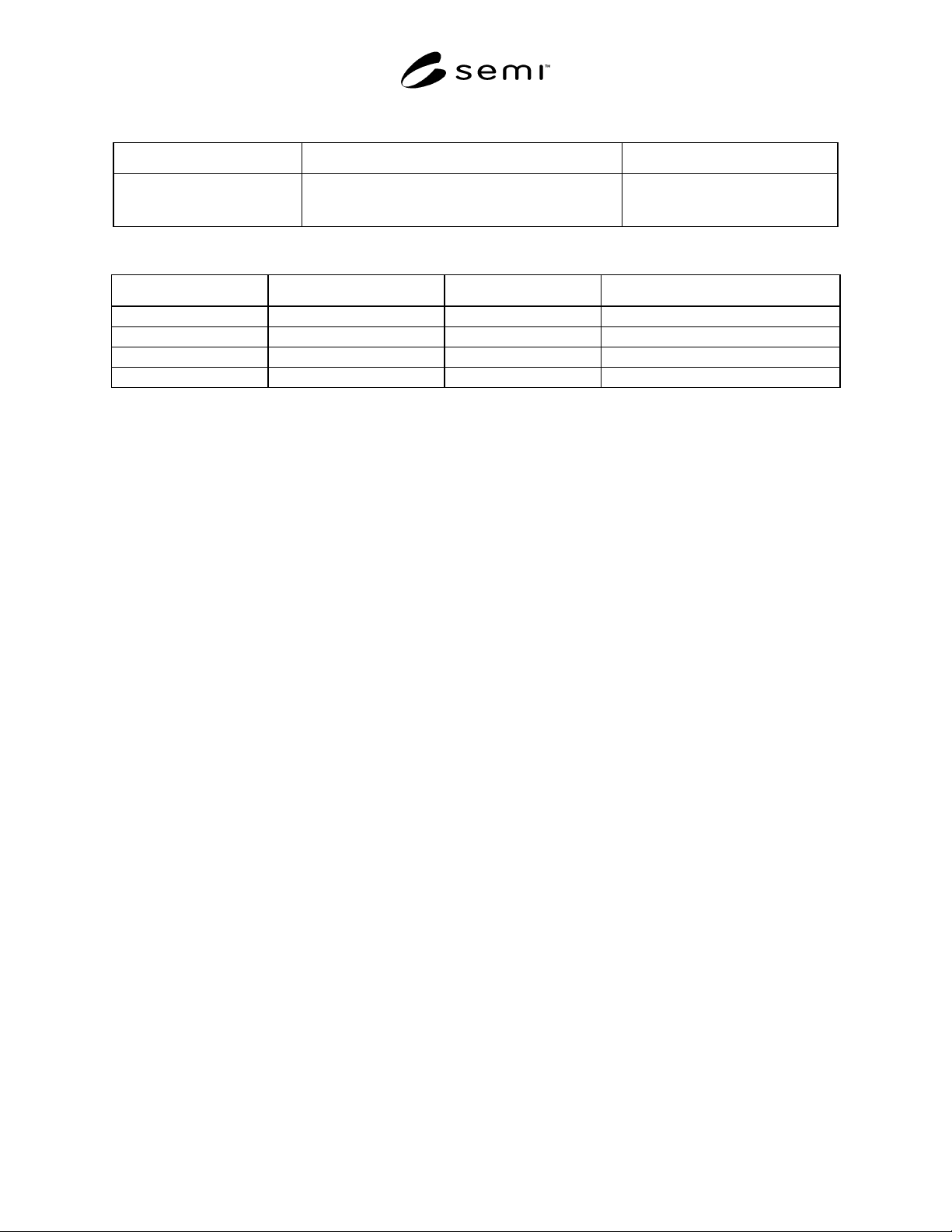
7.4.3.5.1 The State Model shows behavior associated
with CIM Framework interfaces as changes in state that
result from specific events. The required behavior for
an interface is conveyed through UML State Diagrams
[UML] and textual tables that offer supporting details.
Under this notation which is based on Harel Statecharts,
states may be divided into substates, thereby forming a
hierarchy of states. Substates must be one of two types,
termed AND substates (representing concurrency) and
exclusive OR substates (representing a finer breakdown
of a parent state).
7.4.3.5.2 Object State Tables provide supplementary
(to the State Diagram) state information including
descriptive state definitions, state query mechanisms,
the triggers effecting state transition, and the actions
resulting from state transitions.
7.4.3.5.3 Object State Definitions and Query Table
7.4.3.5.3.1 The Object State Definition and Query
Table provide supplementary information to the State
Diagram.
SEMI E81-0600 © 1999, 200037
Bank Customer : B ATM : A
1: requestSession( )
2: requestIdentification( )
3: provideIdentification(idNum ber)
4: verifyIdentification( )
Figure 24
Component Interaction Model Example
State Name
Composite State
State 1 State 2State 1 State 2
s ta t e tr a n si ti on
entry point
Figure 25
State Diagram
7.4.3.5.3.2 Table 1 provides a detailed description of
each object state and identifies the query mechanism for
determining if the object is in that state. Given the
example provided in this section, an entry in the State
Definitions and Query Table would appear as shown.
7.4.3.5.4 Object State Transition Tables
7.4.3.5.4.1 Another supplement to the state model is
the Object State Transition Table (Table 2).
7.4.3.5.4.2 It lists the transition from the state diagram
identified by the starting and ending states, and the
event that causes the transition between these states.
7.4.3.5.4.3 Within the CIM Framework specification,
only those triggers and state changes relevant to
external interfacing are shown to help define how an
external entity (in this case a driver) interoperates with
an object (in this example an automobile).
7.4.3.5.4.4 While this table defines triggers for state
transitions, there is no guarantee that the transition will
take place in response to the trigger. In the above
example, if the car is out of gas the engine will not go
to the running state; if the light is burned out, it will not
transition to the on state; depressing the accelerator
pedal when the auto is in the off state will have no
effect, etc. In the CIM Framework, object state can be
queried to ensure successful transitioning in response to
a triggering message. Events are also used in some
cases to inform the client of a transition or change of
state.
SEMI E81-0600 © 1999, 2000 38
Table 1 Object State Definitions and Query Table Example
State Definition Query for State Via
ENGINE RUNNING In this state, the automobile's engine is running. boolean isEngineRunning ( );
sent to instance of Automobile.
Returns true.
Table 2 Object State Transition Table Example
Current State Trigger New State Action
ENGINE STOPPED turn ignition key to right ENGINE RUNNING tachometer indicates positive RPM
ENGINE RUNNING turn ignition key to left ENGINE STOPPED tachometer indicates zero RPM
LIGHTS OFF turn light switch on LIGHTS ON driving at night is enabled
LIGHTS ON turn light switch off LIGHTS OFF driving at night disabled
7.4.4 Textual Specification Language
7.4.4.1 The textual notations used to specify the
framework in this specification, include the following:
• Interface Definition Language (IDL).
• Interface Definition Format.
7.4.4.2 Interface Definition Language (IDL)
7.4.4.2.1 Specifications of CIM Framework
components are composed mainly of interfaces. The
specifics of each interface, while also represented in the
UML-based Component Information Model, are
rigorously specified using OMG IDL. The IDL for CIM
Framework interfaces shall be complete and consistent
as verified by automated IDL compilers. The IDL
portion of SEMI specifications will be available in a
text file format to facilitate such validation and use with
IDL compiler technologies.
7.4.4.2.2 This explanation of IDL is addressed to its
use as a rigorous specification tool. The considerations
of mapping the specifications to an implementation
infrastructure are addressed in SEMI E96.
7.4.4.2.3 Common Object Broker Architecture
(CORBA) [CORBA][CIMArch] defines the architecture
which enables and regulates interoperability between
objects and applications across heterogeneous
languages and computer boundaries. In all Object
Management Group (OMG) specifications, services are
defined as object interfaces expressed in the OMG's
IDL. CORBA standards define IDL and its mapping to
implementation languages (for example, C, C++,
Smalltalk, and Java).
7.4.4.2.4 IDL is a compilable language that describes
the operations that are specified for an interface. The
notation is independent of the language in which the
methods that implement an interface’s operations are
written. This goal is achieved by mapping between the
IDL syntax and whatever language is used to implement
client and server objects. Because IDL is designed
purely for interface specification, it omits the flow
control and operator constructs of an implementation
language. Object classes can implement an interface
differently as long as their behavior conforms to the
interface specification.
7.4.4.2.5 IDL obeys the same lexical rules as C, while
introducing a number of keywords specific to a
distributed system. As IDL is mapped to object-oriented
languages, new constructs will appear. A brief
discourse on some of the keywords and concepts used
in this specification follows. In the examples, words in
italics are user supplied, others are IDL-defined
keywords.
7.4.4.3 Interface Specification Format
7.4.4.3.1 The OMG defines an object’s interface as “a
listing of the operations and attributes that an object
provides. This includes the signatures of the operations,
and the types of the attributes. An interface
specification ideally includes the semantics as well”
[OMA]. The CIM Framework Specification builds
upon this definition to provide additional semantic
information for an interface. These semantics are
captured in an interface description. This section
describes the format of an interface. Each description of
an interface follows this format. The format includes
the following:
• Name — The capitalized noun following the word
“Interface:”
• Inherited Interface — The capitalized noun after
the words “Inherited Interface:”
• Description — A definition of the interface giving
its form and function.