semi合集-English.pdf - 第614页
SEMI E84-0305 © SEMI 1999, 2005 12 Table 5 Boundary Description Description A Active equipment starts specifying the port. B Active equipment tries to engag e with the passive equipm ent in a transfer validating its requ…
SEMI E84-0305 © SEMI 1999, 2005 11
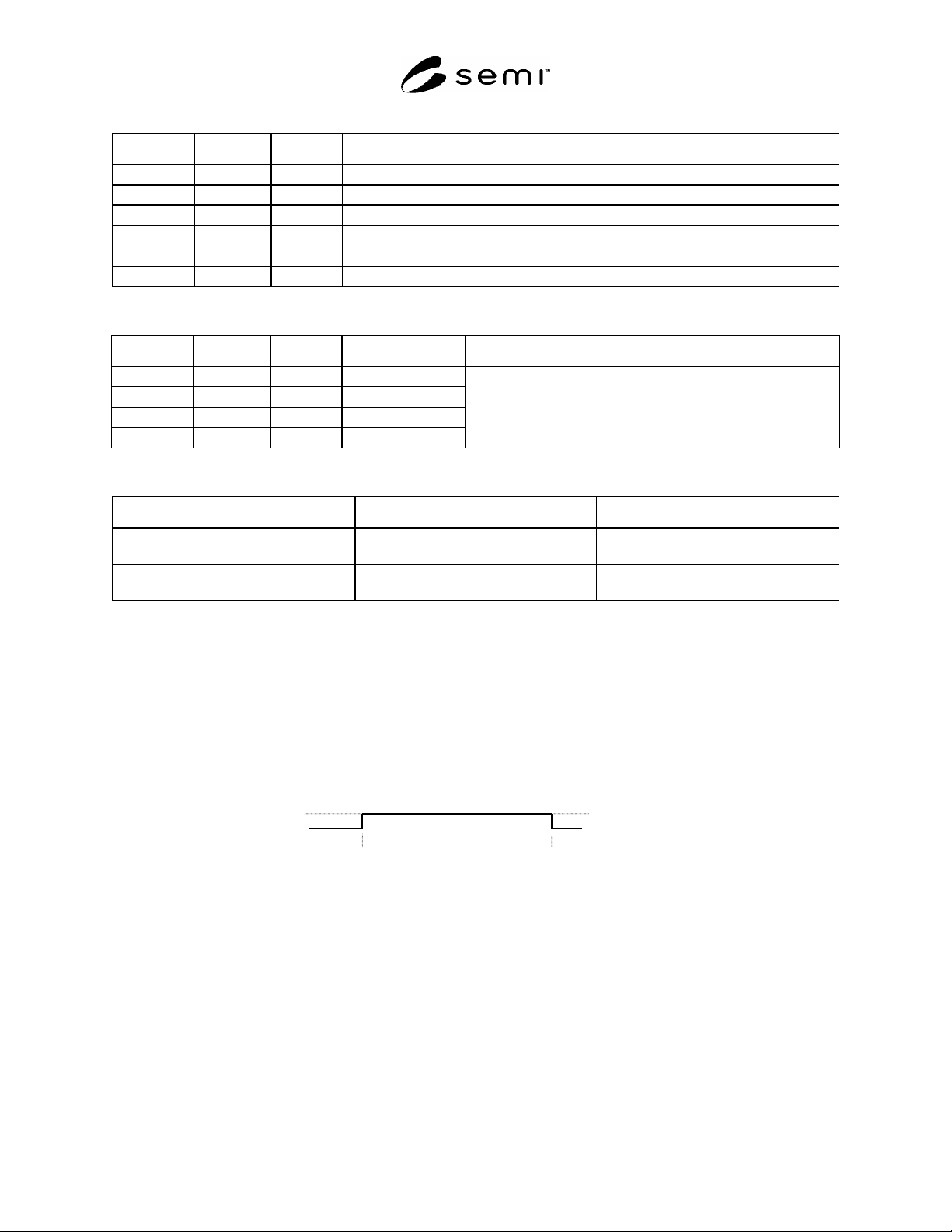
Table 2 Example of the Load Port Specified by CS_0/CS_1 Signal (one PI/O per 2 load ports)
PI/O# CS_0 CS_1 Load Port Comment
1 ON OFF LP1 Single Handoff or Continuous Handoff
1 OFF ON LP2 Single Handoff or Continuous Handoff
1 ON ON LP1 & LP2 Simultaneous Handoff
2 ON OFF LP3 Single Handoff or Continuous Handoff
2 OFF ON LP4 Single Handoff or Continuous Handoff
2 ON ON LP3 & LP4 Simultaneous Handoff
Table 3 Example of the Load Port Specified by CS_0/CS_1 Signal (one PI/O per load port)
PI/O# CS_0 CS_1 Load Port Comment
1 ON OFF LP1
2 ON OFF LP2
3 ON OFF LP3
4 ON OFF LP4
When a PI/O is dedicated to a single load port, CS_0 is always
on, CS_1 is always off.
Table 4 Example of the Load Port Specified by VS_0/VS_1 Signal (One PI/O per 2 load ports)
Left Load Port Right Load Port
VS_0 ON
OFF
×
VS_1 ON
OFF
×
= Select
× = Not Select
= Do not care
6.2 Carrier Handoff Sequences
6.2.1 The signals of the enhanced carrier handoff parallel I/O interface compliant to this specification must follow
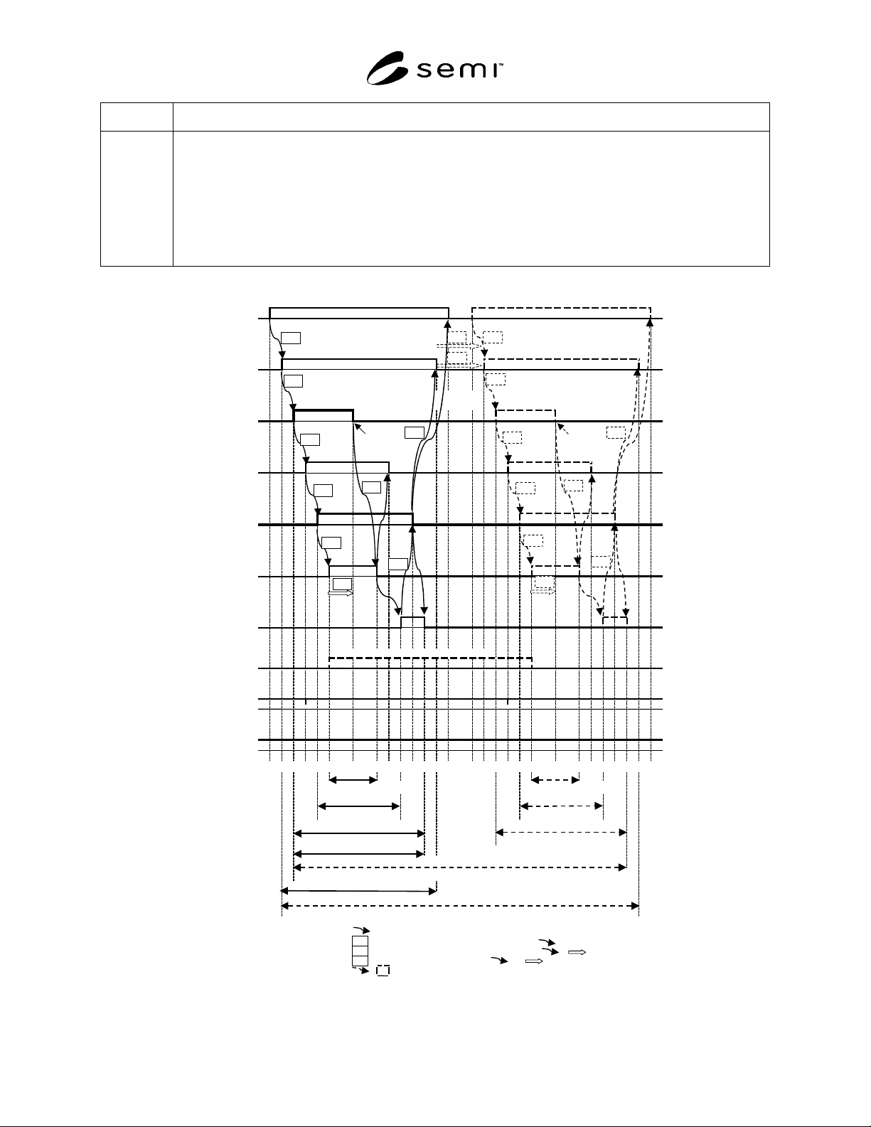
these defined sequences. The time diagrams of the carrier handoff sequences are shown in Figures 10–29. Figure 10
is a summary of various handoffs including load/unload and single/simultaneous/continuous handoff sequences.
Figure 11 is a transition model of zones. Each change in signal state is numbered in the time diagrams. These
numbers are for reference only and may not correspond with the handoff steps or signal order requirements in ¶6.2.
Event A Event B
signal on
signal off
Figure 9
Key for Timing Diagram Signal States
6.2.2 Load/Unload Boundaries
6.2.2.1 Changes in the signal state are shown and described as boundaries to clarify each step during handshake and
transfer as seen in the signal time diagram in Figure 10 and Tables 5 and 6.
SEMI E84-0305 © SEMI 1999, 2005 12
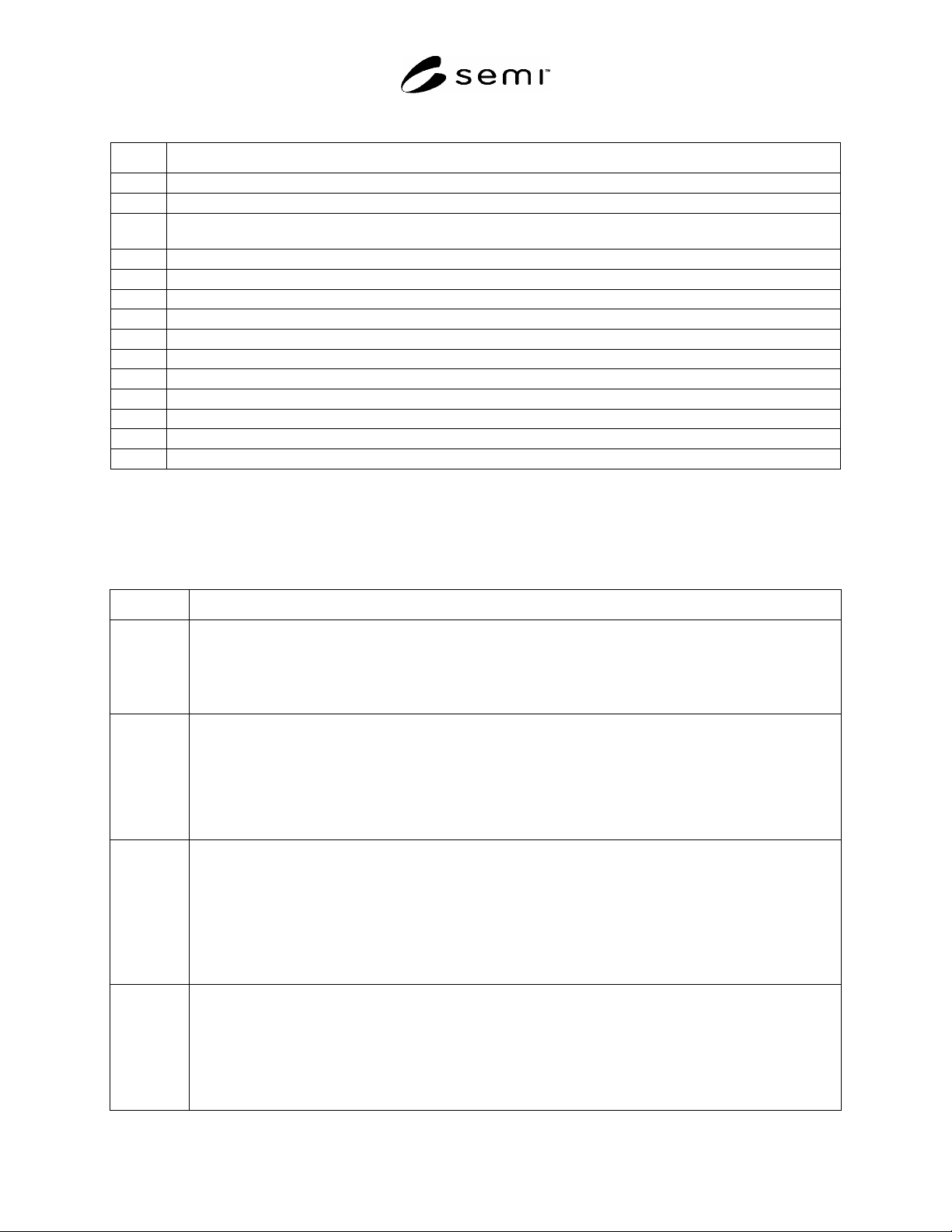
Table 5 Boundary Description
Description
A Active equipment starts specifying the port.
B Active equipment tries to engage with the passive equipment in a transfer validating its request.
C Passive equipment indicates to the active equipment that it accepts to be engaged in a transfer based in its load port
condition (Load or unload).
D Active equipment agrees with passive equipment intent and indicates is ready for the transfer.
E Passive Equipment replies it is also ready for transfer.
F Start of physical handoff (Assign/resign continuous handoff).
G Passive equipment detects that a carrier has been placed/removed.
H Active equipmrent signals the end of physical handoff.
I Active equipment terminates request for transfer.
J Active equipment signals that the transfer engagement has completed.
K Passive equipment indicates that no further transfer activity will occur between them.
L Active equipment signals acknowledgement of completion of intent to transfer.
M Active equipment indicates passive equipment no intent of further handshake.
N Active equipment drops port request signal to leave.
6.2.3 Zone
6.2.3.1 Specific time intervals are clarified in nesting structure and defined as zones. Each zone is defined in Figure
10 and Table 6.
Table 6 Zones
Zone Definition/Description
Handshake
Active
B to M
This zone indicates the state of communication that active equipment is intending to communicate with passive
equipment.
Start at: VALID ON
End at: VALID OFF (last VALID OFF for continuous handoff)
Requirements – Passive equipment is not bounded to any transfer activity previous to or after these transitions.
Handshake
Engaged
C to L
This zone is included in “Handshake Active”. This zone indicates the state of communication that passive
equipment is responding to active equipment.
Start at: L_REQ ON or U_REQ ON
End at: COPY OFF (last COMPT OFF for continuous handoff)
Requirement – Passive equipment does not perform any physical activity that changes the load or unload
conditions in the equipment after setting L-REQ or U-REQ. Passive equipment shall perform necessary operation
such as clamping or docking after the load operation only after it sets Ready signal OFF.
Handoff
Request
C to L
This zone is included in “Handoff Engaged”. The zone indicates the state of communication that load or unload is
engaged between active equipment and passive equipment.
Load Motion is engaged if L_REQ is ON and unload motion is engaged if U_REQ is ON.
Start at: L_REQ ON or U_REQ ON
End at: COMPT OFF
Requirement – FOUP shall be kept Docked/Clamped while this request is becoming active and passive equipment
shall not perform any physical action during the physical handoff other than the actions required to be ready for
active handoff.
Handoff
Active
E to J
This zone is included in “Handoff Request”. This zone indicates the state if communication and physical condition
that passive equipment is ready for active equipment to perform “Physical Handoff”.
Start at: READY ON
End at: COMPT ON
Requirement – Passive equipment is required to undock/unclamp the FOUP and place it at the load port if the
FOUP is not at the port prior to enter this zone during unload. Passive equipment shall not activate dock/undock
motion and clamp/unclamp motion during loading in this zone.
SEMI E84-0305 © SEMI 1999, 2005 13
Zone Definition/Description
Physical
Handoff
F to H
This zone is inclued in “Handoff Active”. This zone indicates that the active equipment is engaged in physically
delivering or removing FOUP to/from the equipment.
One carrier is loaded or unloaded if CS_0 or CS_1 is ON.
Two carriers are loaded or unloaded if CS_0 or CS_1 are ON
Start at: BUSY ON
End at: BUDY OFF
Requirements – Active equipment is required to start the movement to load/unload carrier and completely move
out from handoff conflict area.
CS_0
(CS_0 ON to specify left load port, CS_1 ON to specify right load port,
CS_1
CS_0 and CS_1 ON to specify simultaneous handoff)
(A to P)
VALID
(A to P)
L_REQ
(L_REQ ON to assign load port for LOAD
U_REQ
U_REQ ON to assign load port for UNLOAD)
(P to A)
carrier is carrier is
detected detected
TR_REQ
(A to P)
READY
(P to A)
BUSY
(A to P)
COMPT
(A to P)
CONT
(CONT ON to assign continuous handoff)
(A to P)
HO_AVBL
(P to A)
ES
(P to A)
<boundary>
A B C D E F
G H I J K L M N A B C D E F G H I J K L M N
<zone>
Physical Handoff Physical Handoff
Handoff Active
Handoff Active
Handoff Request Handoff Request
Handshake Engaged (non-continuous)
Handshake Engaged (non-continuous)
Handshake Active (non-continuous)
Handshake Active (continuous)
Relation of signals
Active Equipment Timer related to
Passive Equipment Timer related to or
Delay Timer related to or
for continuous handoff use only
TD1
TP6 TD0
TP1
TP2
TP3
TP4
TP5
TA1
TA2
TA3
TD0
TP1
TP2
TP3
TP4
TP5
TA1
TA2
TA3
TDx
TAx
TPx
Figure 10
Summary of Time Diagram