semi合集-English.pdf - 第3382页
SEMI E132.1-0305 © SEMI 2005 9 <xs:element name =" Parent "> < xs:complexType > < xs:sequence > < xs:element name =" Child1 "/> < xs:complexType > < xs:sequence minOcc…
SEMI E132.1-0305 © SEMI 2005 8
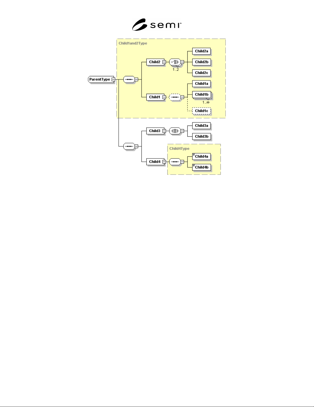
Figure 1
XML Schema Example Diagram
6.3.4 To simplify a diagram or help focus on a particular aspect, detail may be hidden. The 8-sided symbols have a
small square on the right end. If a minus sign “-” is in the box, then all detail is shown. If the box contains a plus
sign “+”, then all detail to the right of that symbol is hidden. The example has no hidden detail.
6.3.5 The yellow (or grey if printed in monochrome) boxes indicate the use of other defined types. So, Child4 is of
type “Child4Type”. Child4Type defines Child4a and Child4b. This detail may be hidden in the diagram. Object
oriented inheritance is typically represented in XML as type extension. In Figure 1, ParentType extends
Child1and2Type by adding a sequence that includes Child3 and Child4.
6.3.6 Reading Figure 1 would yield the following additional information:
1. Child1and2Type is an ordered sequence of two items: Child2 and Child1.
2. Child1 contains an optional ordered sequence of Child1a, one or more Child1b, and (optionally) Child1c.
3. Child2 contains a choice of one or two of the following: Child2a, Child2b, and Child2c.
4. Child3 contains an unordered sequence of Child3a and Child3b.
6.4 XML Schema Sample
6.4.1 The sample XML Schema for the example shown in Figure 1, is presented below. Refer to the XML
documentation referenced in ¶4.3 for a complete description of the syntax and semantics of XML Schema.
SEMI E132.1-0305 © SEMI 2005 9
<xs:element name="Parent">
<xs:complexType>
<xs:sequence>
<xs:element name="Child1"/>
<xs:complexType>
<xs:sequence minOccurs="0">
<xs:element name="Child1a"/>
<xs:element name="Child1b" maxOccurs="unbounded"/>
<xs:element name="Child1c" minOccurs="0"/>
</xs:sequence>
</xs:complexType>
</xs:element>
<xs:element name="Child2">
<xs:complexType>
<xs:choice maxOccurs="2">
<xs:element name="Child2a"/>
<xs:element name="Child2b"/>
<xs:element name="Child2c"/>
</xs:choice>
</xs:complexType>
</xs:element>
<xs:element name="Child3">
<xs:complexType>
<xs:all>
<xs:element name="Child3a"/>
<xs:element name="Child3b"/>
</xs:all>
</xs:complexType>
</xs:element>
</xs:sequence>
</xs:complexType>
</xs:element>
Figure 2
XML for Sample
6.5 Translating UML to WSDL
6.5.1 In general, UML interface classes defined in the abstract specification are translated into WSDL as portType
definitions, and each portType definition has a corresponding WSDL binding definition. The following tables show
the convention used for documenting the WSDL port type and binding definitions for a given UML interface class.
Table 5 Example Interface WSDL Port Type Table
Class Name <UML interface name from abstract specification>
WSDL Port Type Name <port type name used in WSDL>
SEMI E125 Operation
WSDL Operation
<operation name from UML interface>
<WSDL port type operation name>
Table 6 Example Interface WSDL Binding Table
SEMI E125 Class Name <UML interface name from abstract specification>
WSDL Binding Name <binding name used in WSDL>
SOAP Binding Style <RPC or document>
SOAP Transport <transport identifying URI>
6.5.2 Each operation defined for a given UML interface class has a corresponding operation definition and binding.
Operations are described using a table format illustrated by Table 7 and Table 8.
SEMI E132.1-0305 © SEMI 2005 10
Table 7 Example Operation Binding Table
SOAPAction <the SOAPAction HTTP header value to be used for this operation>
Input Headers (WSDL Message, Required)
<the name of the WSDL message providing input headers, and whether or
not the headers are required>
Output Headers (WSDL Message, Required)
<the name of the WSDL message providing output headers, and whether or
not the headers are required>
Table 8 Example PortType Operation Table
Input Message Name <WSDL message name used as input for the WSDL port type operation>
Output Message Name <WSDL message name used as output for the WSDL port type operation>
7 SEMI E132 Authentication Mapping to SSL
7.1 SSL Overview
7.1.1 This section describes the use of SSL security protocol and supporting technology to implement the
authentication scheme described in SEMI E132. SSL is application protocol independent and transparently supports
any higher layered transport protocols such as SOAP over HTTP.
7.1.2 Figure 3 presents the basic message flow (handshake) of SSL to establish a secure connection and how it
maps to the SEMI E132 authentication messages, please refer to the SSL documentation referenced in ¶4.4 for
complete specification on SSL. This specification defines several restrictions on the capabilities of SSL to the
minimum necessary to support SEMI E132 authentication. These restrictions are described in more detail in the
following section.
7.1.3 SEMI E132 Restrictions on SSL
7.1.3.1 X.509 v3 public key certificates as defined by RFC 2459 must be used to establish equipment and client
identities, see X.509 documentation referenced in ¶4.4 for complete details of X.509 structure and content. The
certificate is sent when required during the SSL handshake.
7.1.3.2 Mutual authentication is required. Equipment shall always send its certificate and request for the client’s
certificate as part of the SSL handshake. Correspondingly, client will send its own certificate and the certificate
verify message to equipment to allow client authentication.