semi合集-English.pdf - 第6212页
SEMI G42-0996 © SEMI 1986, 2004 15 Figure 14 Test Board Orientation Inside Wind Tunnel NOTICE: SEMI makes no warranties or represen tations as to the suitability o f the standards set forth herein for any particular appl…
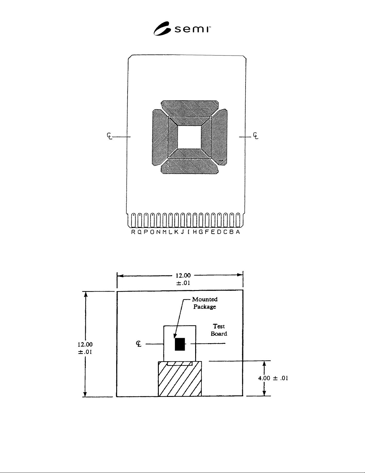
SEMI G42-0996 © SEMI 1986, 2004 14
Figure 12
Location of Package While Mounting on Test Board (QFP)
Figure 13
Test Board Positioning Inside Measuring Chamber
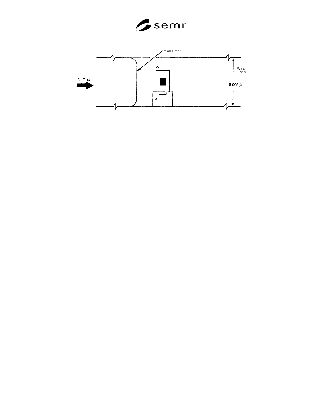
SEMI G42-0996 © SEMI 1986, 2004 15
Figure 14
Test Board Orientation Inside Wind Tunnel
NOTICE: SEMI makes no warranties or representations as to the suitability of the standards set forth herein for any
particular application. The determination of the suitability of the standard is solely the responsibility of the user.
Users are cautioned to refer to manufacturer’s instructions, product labels, product data sheets, and other relevant
literature respecting any materials mentioned herein. These standards are subject to change without notice.
The user’s attention is called to the possibility that compliance with this standard may require use of copyrighted
material or of an invention covered by patent rights. By publication of this standard, SEMI takes no position
respecting the validity of any patent rights or copyrights asserted in connection with any item mentioned in this
standard. Users of this standard are expressly advised that determination of any such patent rights or copyrights, and
the risk of infringement of such rights, are entirely their own responsibility.
Copyright by SEMI® (Semiconductor Equipment and Materials
International), 3081 Zanker Road, San Jose, CA 95134. Reproduction o
f
the contents in whole or in part is forbidden without express written
consent of SEMI.

SEMI G43-87 © SEMI 1986, 19871
SEMI G43-87
TEST METHOD FOR JUNCTION-TO-CASE THERMAL RESISTANCE
MEASUREMENTS OF MOLDED PLASTIC PACKAGES
1 Purpose
The purpose of this test is to determine the thermal
resistance of molded plastic packages using thermal test
chips. This test method deals only with junction-to-case
measurements of thermal resistance and limits itself to
fluid bath testing environments. For this test,
conduction through the leads is minimized, thus
providing information on the ability of the plastic
package material to dissipate heat. Due to the
thermophysical properties of the heat transfer fluids
used and the effects of the variable nature of the fluid-
stirring and package-mounting procedures, this test
method should only be used for comparing the thermal
characteristics of plastic packages in the same fluid bath
system.
2 Applicable Documents
2.1 SEMI Specification
SEMI G32 — Guideline for Unencapsulated Thermal
Test Chip
3 Definitions
The following definitions and symbols shall apply for
the purpose of this test:
case temperature, T
C
— in degrees Celsius. The case
temperature is the temperature at a specified accessible
reference point on the package in which the
microelectronic chip is mounted.
junction temperature, T
J
— in degrees Celsius. The
term is used to denote the temperature of the
semiconductor junction in the microcircuit in which the
major part of the heat is generated. For purposes of this
test, the measured junction temperature is only
indicative of the temperature in the immediate vicinity
of the element used to sense the temperature.
power dissipation, P
H
— in watts, is the heating power
applied to the device causing a junction-to-reference
point temperature difference.
thermal resistance, junction to specified reference
point, R
θJR
— in degrees Celsius/watt. The thermal
resistance of the microcircuit is the temperature
difference from the junction to some reference point on
the package divided by the power dissipation P
H
.
temperature-sensitive parameter, TSP — the
temperature-dependent electrical characteristic of the
junction under test which can be calibrated with respect
to temperature and subsequently used to detect the
junction temperature of interest.
4 Apparatus
The apparatus required for these tests shall include the
following as applicable to the specified test procedures:
a. Thermocouple material shall be copper-constantan
(type T) or equivalent, for the temperature range
-100 to + 300°C. The wire size shall be no larger
than AWG size 30. The junction of the
thermocouple shall be welded to form a bead rather
than soldered or twisted. The accuracy of the
thermocouple and associated measuring system
shall be ± 0.5°C.
b. Suitable electrical equipment as required to provide
controlled levels of conditioning power and to make
the specified measurements. The instrument used to
electrically measure the temperature-sensitive
parameter shall be capable of resolving a voltage
change of 0.5 mV.
c. Controlled temperature chamber or fluid bath
capable of maintaining the specified reference point
temperature to within ± 0.5°C of the preset
(measured) value. A typical temperature-controlled
fluid bath assembly is presented for illustrative
purposes only.
4.1 Fluid Bath Assembly — A typical temperature-
controlled fluid bath for thermally characterizing the
microelectronic device under test is shown in Figure 1.
In this figure, the package is mounted in a fluid bath
separate from the fluid circulator, although it can be
immersed directly in an integrated fluid circulator/bath
unit. The fluid in the bath should be continuously
stirred or agitated to ensure the required temperature
stability and uniformity. Since this working fluid is
being used as an infinite heat-sink, the case-to-fluid
(ambient) temperature difference at the case
temperature reference point of interest should be
minimized, i.e., ≤ 20°C. For case-to-fluid temperature
differences > 20°C, accuracy and repeatability
difficulties may occur due to a large variable
temperature gradient in the fluid film boundary layer at
the package-fluid interface. The case-to-fluid
temperature difference can be minimized by increasing