semi合集-English.pdf - 第3875页
SEMI F24-0697 © SEMI 1997, 2003 5 NOTICE: SEMI makes no warranties or representations as to the suitability o f the standards set forth herei n for any particul ar applicat ion. The determination of the suitability of th…
SEMI F24-0697 © SEMI 1997, 2003 4
RELATED INFORMATION 1
NOTES ON ASPIRATION EFFICIENCIES OF WALL TAP SAMPLE
PORTS
NOTICE: This related information is not an official part of SEMI F24 and is not intended to modify or supercede the official
standard. Determination of the suitability of the material is solely the responsibility of the user.
R1-1 Introduction
R1-1.1 Isokinetic sample probes are usually not
provided in speciality gas systems. Particle sampling is
usually performed using wall tap sample ports. Wall
tap sample ports are oriented 90° to the process line
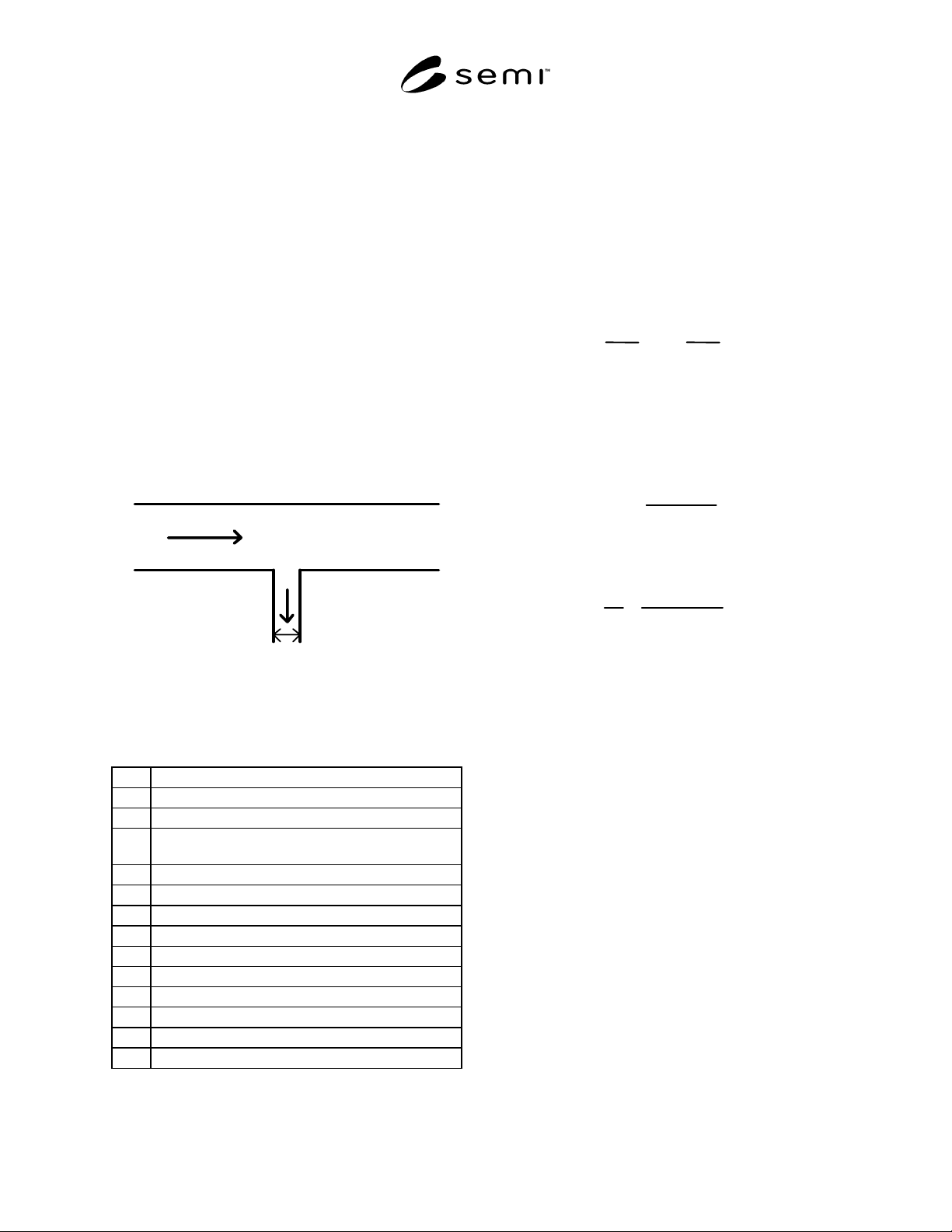
flow as shown in Figure R1-1. Non-isokinetic flow into
the sample tube results from the 90° change in flow
direction. Additional deviation from isokinesis can
result from stream tube contraction or expansion when
the velocities U and v are not equal. The effects of
non-isokinetic flow on the measurement should be
checked. The particle sampling process should be
performed with an aspiration efficiency close to 1.
Process Line
v, C
To Sampling System
Wall Tap
D
U, Co, p
Figure R1-1
Schematic Diagram of Process Line and Wall Tap
Sample Port
R1-2 Variables
d
p
= Diameter of particle (cm)
ρ
p
= Intrinsic density of particle (g/cm
3
)
η = Dynamic viscosity of the gas (g/s-cm)
λo = Mean free path of the gas at atmospheric pressure
(cm)
p = Pressure of the gas (Pa)
P
O
= Atmospheric pressure (= 1 × 10
5
Pa)
D = Diameter of wall tap sample tube (cm)
U = Average velocity of the process line flow (cm/s)
v = Average velocity of the sample line flow (cm/s)
C* = Stokes-Cunningham slip correction factor
S
tk
= Stokes number
R = Velocity ratio
Co = Particle concentration in the process line (cm
–3
)
C = Particle concentration in the sample line (cm
–3
)
R1-3 Calculations
R1-3.1 The Stokes-Cunningham slip correction factor
is calculated for particles in the size range of interest:
C* = 1 + 2.492
p
o
λ
o
pd
p
+
0. 84
p
o
λ
o
pd
p
e
−
0
.
435pd
p
/ p
o
λ
Calculate the velocity ratio and Stokes number. The
intrinsic particle density may assume a worst case value
of 10 g/cm
3
:
R
=U/v
S
tk
=
d
p
2
ρ
p
UC*
18
η
D
A wall tap sample port can be approximated as a
sampling probe oriented 90° to the flow. Calculate the
aspiration efficiency:
C
Co
=
1
1 + 8S
tk
R
1/2
Repeat the calculations for particle sizes in the range of
interest. When the aspiration efficiency is significantly
different from 1, the calculated efficiency should be
used to correct the measured particle concentration, C.
R1-4 References
Stevens, D. C. Review of Aspiration Coefficients of
Thin-Walled Sampling Nozzles. J. Aerosol Sci.,
17(4):729–743, 1986.
Vincent, J. H., D. C. Stevens, D. Mark, M. Marshall,
and T. A. Smith. On the Aspiration Characteristics of
Large-Diameter, Thin-Walled Aerosol Sampling Probes
at Yaw Orientations With Respect to the Wind. J.
Aerosol Sci., 17(2):211–224, 1986.
SEMI F24-0697 © SEMI 1997, 2003 5
NOTICE: SEMI makes no warranties or
representations as to the suitability of the standards set
forth herein for any particular application. The
determination of the suitability of the standard is solely
the responsibility of the user. Users are cautioned to
refer to manufacturer's instructions, product labels,
product data sheets, and other relevant literature,
respecting any materials or equipment mentioned
herein. These standards are subject to change without
notice.
By publication of this standard, Semiconductor
Equipment and Materials International (SEMI) takes no
position respecting the validity of any patent rights or
copyrights asserted in connection with any items
mentioned in this standard. Users of this standard are
expressly advised that determination of any such patent
rights or copyrights, and the risk of infringement of
such rights are entirely their own responsibility.
Copyright by SEMI® (Semiconductor Equipment and Materials
International), 3081 Zanker Road, San Jose, CA 95134. Reproduction o
f
the contents in whole or in part is forbidden without express written
consent of SEMI.
SEMI F25-0697 © SEMI 1997, 2003 1
SEMI F25-0697 (Reapproved 0303)
PARTICLE SPECIFICATION FOR GRADE 10/0.2 OXIDANT SPECIALTY
GASES
This specification was technically approved by the Global Gases Committee and is the direct responsibility of
the North American Gases Committee. Current edition approved by the North American Regional Standards
Committee on October 25, 2002. Initially available at www.semi.org December 2002; to be published March
2003. Originally published June 1997.
1 Purpose
1.1 The purpose of this document is to set a maximum
permissible particle concentration for 10/0.2 grade
oxidant specialty gases and to describe a reference
method for its verification.
2 Scope
2.1 This document applies only to oxidant gases
delivered through specialty gas systems at pressures up
to 8 × 10
5
Pa (8 atmospheres). This method is not
suitable for direct sampling from high pressure
cylinders at pressures above 8 × 10
5
Pa (8
atmospheres). This document applies only to the
following gas:
Oxygen (O
2
)
Nitrous Oxide (N
2
O)
Nitrogen Trifluoride (NF
3
)
2.2 This standard does not purport to address safety
issues, if any, associated with its use. It is the
responsibility of the users of this standard to establish
appropriate safety and health practices and determine
the applicability of regulatory or other limitations prior
to use.
3 Referenced Standards
3.1 SEMI Standard
SEMI C6.2 — Particle Specification for Grade 20/0.02
Oxygen Delivered as Pipeline Gas
3.2 JIS Standard
1
JIS B 9921 — Japanese Industrial Standard (1989),
“Light Scattering Automatic Particle Counter”
NOTICE: Unless otherwise indicated, all documents
cited shall be the latest published versions.
1 Japanese Industrial Standards, Available through the Japanese
Standards Association, 1-24, Akasaka 4-Chome, Minato-ku, Tokyo
107-8440, Japan. Telephone: 81.3.3583.8005; Fax: 81.3.3586.2014
Website: http://www.jsa.or.jp
4 Terminology
4.1 Variables
V
Mi
= Volume of the i
th
sample interval of the system gas
V
Bi
= Volume of the i
th
sample interval of the background
X
Mi
= Concentration of particles observed in the i
th
sample o
f
interval of the system gas
X
Bi
= Concentration of particles observed in the i
th
sample o
f
interval of the background
N
M
= Number of sample intervals of the system gas
N
B
= Number of sample intervals of the background
M
X=
Average observed concentration of counts in the
system gas sample
B
X=
Average observed concentration of background counts
C
X=
Calculated concentration of particles in the system gas
S
M
=
Standard deviation of
M
X
S
B
=
Standard deviation of
B
X
S
C
=
Standard deviation of
C
X
4.2 gas sample volume (V
Mi
, V
Bi
) — The volume of the
sample interval, expressed in standard liters at standard
conditions, 0°C (32°F) and 1 × 10
5
Pa (1 atmosphere)
pressure. Standard cubic feet (SCF) is defined at
21.1°C (70°F) and 1 × 10
5
Pa (1 atmosphere) pressure.
4.3 average observed concentration of counts
(
M
X ,
B
X ) — The average concentration of counts, i.e.:
X
M
=
Σ
X
Mi
N
M
X
B
=
Σ
X
Bi
N
B
4.4 calculated concentration of particles (
C
X ) — The
concentration of particles in the system gas obtained by
correcting the observed concentration in the system gas
for the observed concentration in the background, i.e.:
X
C
= X
M
− X
B
4.5 standard deviation (S
M
, S
B
, S
C
) — A statistical
measure of the spread of the concentration of the counts
or particles. The first two are obtained from the
interval and average concentrations and the number of
intervals, i.e.: