semi合集-English.pdf - 第4333页
SEMI F88-0304 E © SEMI 2004 1 SEMI F88-0304 E SPECIFICATION FOR DIMENSION OF STANDARD SIZE MASS FLOW CONTROLLERS AND MASS FLOW METERS FOR 1.5 INCH TYPE SURFACE MOUNT GAS DI STRIBUTION SYSTEMS This specification was techn…
SEMI F87-0304 © SEMI 2004 6
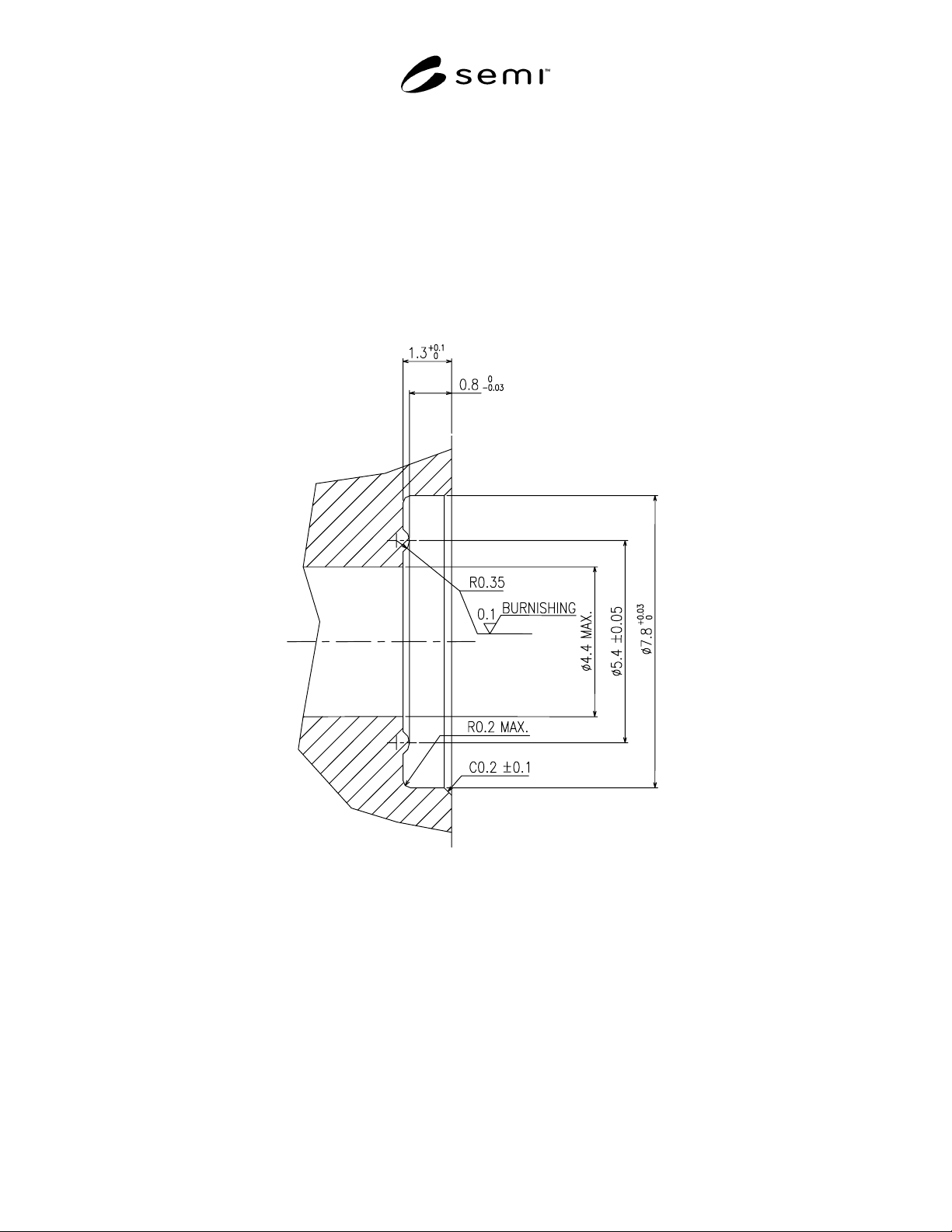
R1-3 Design Example 3
R1-3.1 Seal Design — See Figure R1-3.
R1-3.2 Surface Hardness — The sealing surface (the bottom of the counterbore) has a minimum hardness of 300
Vickers. The hardness may be tested per ISO 6507.
R1-3.3 Surface Roughness — The sealing surface (the bottom of the counterbore) has a surface roughness of 0.1
micrometers Ra max. The surface roughness may be tested per SEMI F37-0299.
R1-3.4 Surface Scratches — The sealing surface (the bottom of the counterbore) is without any lateral scratches
which are visible to non-magnified normal vision.
Figure R1-3
Design Example 3
NOTICE: SEMI makes no warranties or representations as to the suitability of the standards set forth herein for any
particular application. The determination of the suitability of the standard is solely the responsibility of the user.
Users are cautioned to refer to manufacturer' s instructions, product labels, product data sheets, and other relevant
literature, respecting any materials or equipment mentioned herein. These standards are subject to change without
notice.
By publication of this standard, Semiconductor Equipment and Materials International (SEMI) takes no position
respecting the validity of any patent rights or copyrights asserted in connection with any items mentioned in this
standard. Users of this standard are expressly advised that determination of any such patent rights or copyrights, and
the risk of infringement of such rights are entirely their own responsibility.
Copyright by SEMI® (Semiconductor Equipment and Materials
International), 3081 Zanker Road, San Jose, CA 95134. Reproduction o
f
the contents in whole or in part is forbidden without express written
consent of SEMI.

SEMI F88-0304
E
© SEMI 2004 1
SEMI F88-0304
E
SPECIFICATION FOR DIMENSION OF STANDARD SIZE MASS FLOW
CONTROLLERS AND MASS FLOW METERS FOR 1.5 INCH TYPE
SURFACE MOUNT GAS DISTRIBUTION SYSTEMS
This specification was technically approved by the Global Gases Committee and is the direct responsibility of
the Japanese Gases & Facilities Committee. Current edition approved by the Japanese Regional Standards
Committee on November 20, 2003. Initially available at www.semi.org February 2004; to be published
March 2004.
E
This document was modified in May 2004 with committee approval to correct an error made at the pre-
ballot stage. Changes were made to Figure R1-2.
1 Purpose
1.1 This standard establishes the properties and
physical dimensions of mass flow controllers and mass
flow meters for 1.5 inch type surface mount gas
distribution systems.
2 Scope
2.1 This document includes common requirements,
layout, size, detailed specifications, and dimensions of
the components.
2.2 This standard applies to all standard size mass flow
controllers and mass flow meters. The components are
mounted on substrates with fasteners accessible from
the top.
2.3 This standard only applies to components, which
control flow of ≤ 50 slm nitrogen equivalent at 308 kPa
(44.7 psia). This standard also only applies to
components with operating pressures less than 3445
kPa (500 psia) at 20°C.
NOTICE: This standard does not purport to address
safety issues, if any, associated with its use. It is the
responsibility of the users of this standard to establish
appropriate safety and health practices and determine
the applicability of regulatory or other limitations prior
to use.
3 Limitations
3.1 This standard only addresses the component; it
does not address the seals, the sealing system, or the
assembly process and does not guarantee the
performance of the sealing system. The user should be
aware that gas delivery system performance and sealing
system performance are addressed elsewhere in the
SEMI standards.
3.2 The user should be aware that alternative
technologies are commercially available.
3.3 International, national, and local codes, regulations,
and laws should be consulted to ensure that the
equipment meets regulatory requirements in each
location of use.
4 Referenced Standards
4.1 SEMI Standards
SEMI E49.9 — Guide for Ultrahigh Purity Gas
Distribution Systems in Semiconductor Manufacturing
Equipment
SEMI F20 — Specification for 316L Stainless Steel
Bar, Extruded Shapes, Plate, and Investment Castings
for Components Used in High Purity Semiconductor
Manufacturing Applications
4.2 ASME Standards
1
ASME Y14.5 — Dimensioning and Tolerancing
NOTICE: Unless otherwise indicated, all documents
cited shall be the latest published versions.
5 Terminology
5.1 Definitions
5.1.1 components for surface mount — a gas
distribution system component having inlets and outlets
located on the bottom of the component with the
attachment mechanism accessible from the top.
5.1.2 Ra — roughness average. The arithmetic average
of the absolute values of the measure profile height
deviations taken within the sampling length and
measured from the graphical centerline.
6 Common Requirements
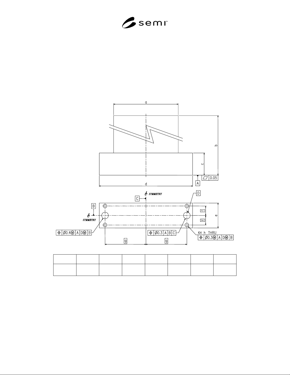
6.1 Dimensional Requirements — All components
shall meet the requirements outlined in Figure 1. All
geometric dimensioning and tolerancing complies with
ASME Y14.5 and/or the applicable ISO standard.
1 American Society of Mechanical Engineers. Three Park Avenue,
New York, NY 10016-5990, USA. Telephone: 800.843.2763
(U.S./Canada), 95.800.843.2763 (Mexico), 973.882.1167 (outside
North America). Website: www.asme.org
SEMI F88-0304
E
© SEMI 2004 2
NOTE 1: All dimensions are in millimeters unless otherwise
noted.
NOTE 2: The through hole of the sealing port will be
elliptical if the through hole is drilled at an angle. In this
case, the diameter shall apply to the major diameter of the
ellipse.
6.2 Material — The material used to manufacture the
base of the components shall comply to SEMI F20 with
the exception that the sulfur content shall comply to
SEMI E49.9.
NOTE 3: SEMI E49.9 was withdrawn. However, a ballot to
combine E49.8 and E49.9 in one single standard was
submitted for SEMICON West 2003.
6.3 Burrs and Sharp Edges — Unless specifically
noted on the drawing, remove all burrs and sharp edges.
6.4 Displays — Removable displays shall stay within
the maximum envelope of the base of the component.
They shall be movable or removable such that they do
not interfere with the access of the mounting fasteners
from above.
a b c d e f g h
82.7
MAX
180
MAX
40
MAX
110
±5.0
38.15
±1.15
15
46
φ5.6
±0.1
UNIT: [mm]
Figure 1
Dimensional Requirements for All Components