semi合集-English.pdf - 第3790页
SEMI F9-0998 © SEMI 1992 , 1998 2 5.2.7 s ubject — To expose to. 5.2.8 s ubmersion tank — A transpar e n t tan k, filled with isopropyl alcohol, to allow observatio n of air leakage from a tube f itting connection. 6 Des…

SEMI F9-0998 © SEMI 1992, 19981
SEMI F9-0998
TEST METHOD TO DETERMINE THE LEAKAGE CHARACTERISTICS
OF TUBE FITTING CONNECTIONS MADE OF FLUOROCARBON
MATERIALS, WHEN SUBJECTED TO A SIDE LOAD CONDITION
1 Purpose
1.1 This method provides a uniform procedure to
determine the leakage characteristics of tube fitting
connections made of fluorocarbon materials, when
subjected to side loading.
2 Scope
2.1 This method can be used to characterize tube
fitting connections on the basis of test data developed
under the conditions described herein, but the results
are not intended to imply a performance rating.
2.2 Tube defined in this method has a circular cross
section and is made of fluorocarbon materials.
2.3 All parts of the tube fittings tested by this method
in contact with the internal fluid are made of
fluorocarbon materials.
2.3.1 Parts such as a nut or gripper are not limited to
being made of a fluorocarbon material.
2.4 Only the seal between the tube and tube fitting
being evaluated is within the scope of this document.
All other, threaded seals are beyond the scope of this
document.
2.5 When using this method for making comparisons
between various tube fittings and/or manufacturers, the
user must be specific in the selection of the tube and
tube fittings to be evaluated.
2.6 The International System of Units (SI) is used as
the standard unit of measure in this document. The U.S.
Customary units are in parentheses for reference
purposes only and may have been rounded to the
nearest whole value.
3 Summary of Method
3.1 Subject tube fitting connections made of
fluorocarbon materials to a side load condition that is a
result of bending the tube in a uniform arc, while
maintaining a specified pressure to the internal cavity of
the fitting and tube.
4 Significance and Use
4.1 In the manufacturing of semiconductor products,
many types of hazardous chemicals and solvents are
required. As a result, tubing and various fitting designs
made of fluorocarbon materials (which are chemically
resistant to these fluids) are used to transport those
fluids. It is important to control the testing process
when evaluating various fitting designs, so that accurate
comparisons of the side load capabilities can be made.
4.2 It is the intent of this method to provide a
procedure in which tube fitting connections made of
fluorocarbon materials will be subjected to extreme side
loading. By using this method, accurate comparisons of
various tube fitting designs can be achieved.
4.3 The results obtained when usin g this method are
applicable only to conditions that specifically duplicate
the procedures used within this document.
4.4 When using this test method, it is assumed that the
test specimens are truly representative of the material
and manufacturing process specified for that product.
Departure from this assumption could introduce
discrepancies that are greater than those introduced by
departure from the details of the procedure outlined in
this method.
5 Terminology
5.1 Acronyms
5.1.1 O.D. — Outside diameter
5.1.2 P/N — Part number
5.2 Definitions
5.2.1 bend radius — The distance from the center of
an imaginary circle on which the arc of the bent tube
falls to a point on the arc.
5.2.2 characterize — To describe the quality of.
5.2.3 kinking — A collapse of the tube wall caused by
excessive bending.
5.2.4 “L” — The tube length required to produce a
uniform 180° arc, at a specified tube bend radius.
NOTE: The symbol “L” is unique in that it is used only in this
test method.
5.2.5 “R” — The theoretical value to determine the
tube bend radius, used during testing.
NOTE: The symbol “R” is unique in that it is used only in this
test method.
5.2.6 side load — A result of bending a tube in a
specified arc, consequently subjecting the tube fitting
connection to a radial stress.
SEMI F9-0998 © SEMI 1992, 1998 2
5.2.7 subject — To expose to.
5.2.8 submersion tank — A transparent tank, filled
with isopropyl alcohol, to allow observation of air
leakage from a tube fitting connection.
6 Description of Test Equipment
6.1 A supply of compressed air. Pressure to be within
± 2% of specified value.
6.2 Isopropyl alcohol.
6.3 An instrument for measuring lengths of tubing
(e.g., tape measure).
6.4 A special apparatus which has a fixture for
attaching the fitting body, while also providing a means
to clamp the free end of tube, to maintain a tube bend
radius.
6.4.1 The apparatus shall allow the test specimen to be
internally pressurized.
6.4.2 The apparatus shall have a transparent
submersion tank capable of containing a fluid for
observing leakage. The minimum fluid level shall be
2.5 cm (1 in) above the test connection.
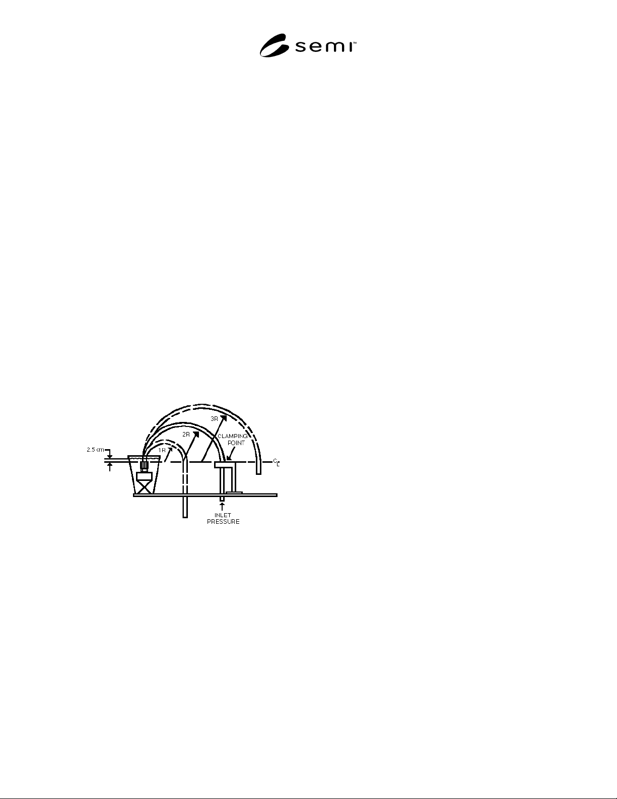
6.5 See Figure 1 for a basic side load test apparatus.
Figure 1
Side Load Test Apparatus
7 Safety Precautions
WARNING: This test method will subject test
specimens to conditions that may exceed the
normal performance rating of the products
under evaluation. Adequate precautions must
be taken to prevent injury to the person
conducting the test.
8 Test Specimens and Conditioning
8.1 Sample Size — A minimum of three specimens
shall be tested.
8.2 Tube — The tubing used for this evaluation shall
be of straight lengths, not previously coiled.
8.3 Specimen Surface — All surfaces of the specimens
shall be free of visible flaws, scratches, or other
imperfections, unless typically found on a
representative sample of the product.
8.4 Specimen Conditioning — All specimens must be
conditioned for a minimum of one hour in an air
environment of 23° ± 2.8°C (73° ± 5°F) prior to being
subjected to pressurization and bending of the tube.
9 Test Procedure
9.1 Perform the following calculation to determine the
“R” value.
9.1.1 For a tubing outside diameter (O.D.) of 1.5 cm
(.59 in) or less: R = Tube O.D. × 5.
9.1.2 For a tubing outside diameter (O.D.) greater than
1.5 cm (0.59 in): R = Tube O.D. × 5.
NOTE: The constants (5 and 10) in Sections 9.1.1 and 9.1.2
were derived from the extrapolation of the actual “Minimum
Bend Radius” of tubing from various manufacturers.
9.2 Perform the calculation in Section 9.2.1 to
determine the tube length required to produce a 180°
arc at a tube bend radius of R.
9.2.1 L = R × 3.14
9.3 Cut three tubes of equal length per the following
formula: 3L + 15 cm (6 in).
9.4 Install a fitting body to the test fixture, in the
submersion tank.
9.5 Install a tube into the fitting body and assemble the
connection per manufacturer’s specification.
NOTE: To prevent side loading of the fitting connection prior
to bending of the tube, provide a method of supporting the
tube.
9.6 Measure from the tube end of the fitting
connection and place a mark on the tube (within ± 1%
of calculated value) in five separate locations as
determined below:
• 0.5L
• 1.0L
• 1.5L
• 2.0L
• 3.0L
9.7 Use the following formula to determine the actual
tube bend radius used and record on test data sheet (see
Related Information 1 for a sample):

SEMI F9-0998 © SEMI 1992, 19983
• 0.5R
• 1.0R
• 1.5R
• 2.0R
• 3.0R
9.8 Fill the submersion tank with isopropyl alcohol to
a minimum height 2.5 cm (1 in) above the top of the
test connection.
9.9 Pressurize the test specimen with an internal air
pressure of 250 kPa (36 psig), regardless of tube size.
9.10 Observe the connection for a minimum of one
minute for bubble leakage (bbl/min) and record on test
data sheet under the column entitled “STRAIGHT”.
9.11 Carefully bend the tube in a uniform 180° arc
with a radius of 3R and clamp the free end to the test
fixture. (See Section 9.7 for specific R value.) Proper
tube length at the clamping point is determined in
Section 9.6.
9.11.1 R value tolerances =
• Tubes with 1.5 cm (0.59 in) O.D. or less = ± 5%
• Tubes with greater than 1.5 cm (0.59 in) O.D. = ±
1%
9.12 Observe the connection for a minimum of one
minute for bubble leakage. Record leakage on the
appropriate area of the test data sheet. If no leakage is
observed, note as “None”.
9.13 Repeat Sections 9.11 and 9.12 for the remaining
tube bend radius of 2R, 1.5R, 1R, and 0.5R, in
descending order.
9.13.1 Should any tube kink prior to achieving 0.5R,
testing of that sample will be discontinued. The radius
at which kinking occurred shall be recorded and noted
as “kink”.
9.13.2 To reduce the effects caused by creep of the
material the total time from initial bending of the tube
until achieving the 0.5R value is to be less than ten
minutes.
9.14 After completion of the first sa mple, replace the
fitting and tube with new specimens and repeat Sections
9.4 through 9.13.2 for a total of three samples.
10 Test Data Sheet
The test data sheet shall include the following
information:
10.1 Date tested.
10.2 Operator and test facility.
10.3 Description of items tested, including:
Tubing — Manufacturer, O.D., wall thickness, part
number, and material type.
Fitting — Manufacturer, type, size, part number, and
material type.
10.4 The actual tube bend radius for each nominal
bend radius.
10.5 The leakage rate, in bubbles per minute, for each
sample at each radius.
NOTE: A sample test data sheet is provided as Related
Information 1.
NOTICE: These standards do not purport to address
safety issues, if any, associated with their use. It is the
responsibility of the user of these standards to establish
appropriate safety and health practices and determine
the applicability of regulatory limitations prior to use.
SEMI makes no warranties or representations as to the
suitability of the standards set forth herein for any
particular application. The determination of the
suitability of the standard is solely the responsibility of
the user. Users are cautioned to refer to manufacturer’s
instructions, product labels, product data sheets, and
other relevant literature respecting any materials
mentioned herein. These standards are subject to
change without notice.
The user’s attention is called to the possibility that
compliance with this standard may require use of
copyrighted material or of an invention covered by
patent rights. By publication of this standard, SEMI
takes no position respecting the validity of any patent
rights or copyrights asserted in connection with any
item mentioned in this standard. Users of this standard
are expressly advised that determination of any such
patent rights or copyrights, and the risk of infringement
of such rights, are entirely their own responsibility.