semi合集-English.pdf - 第7612页
Table 1 Matrix Code Symbol Dimensions Square Arrays for Use on 125 to 200 mm Wafers C 1 , R 1 (µ m) #1 C 2 , R 2 (µ m) #1 # of cells in row or column 16 18 20 16 18 20 125 µ m spacing 1875 2125 2375 2000 2250 2500 150 µ …

4 Terminology
4.1 Definitions
4.1.1 binary values — a dot in the wafer surface
indicates the binary value 1. The absence of a dot, or a
smooth surface surrounding a cell center point,
indicates the binary value 0.
4.1.2 border column — the outermost column of a data
matrix code symbol.
4.1.3 border row — the outermost row of a data matrix
code symbol.
4.1.4 cell center point, of an array — the point at
which the centerline of a row intersects the centerline of
a column.
4.1.5 cell spacing, of an array — the (equal) vertical or
horizontal distance between the cell center points of
contiguous cells.
4.1.6 cell, of a data matrix code symbol — the area
within which a dot may be placed to indicate a binary
value.
4.1.7 center line, of a row or column — the line
positioned parallel to, and spaced equally between, the
boundary lines of the row or column.
4.1.8 central area, of a cell — the area enclosed by a
circle centered at the cell center point; used by code
readers to sense the binary value of the cell.
4.1.9 data matrix code symbol — a two-dimensional
array of square cells arranged in contiguous rows and
columns.
4.1.10 dot — a localized region with a reflectance
which differs from that of the surrounding surface.
NOTE 2: To assure reading efficiency, a minimum contrast
of 30% is required between the reflectance value of a dot and
the surrounding wafer surface. Various densitometers can
provide such measurements nondestructively.
4.1.11 dot misalignment, within a cell — the distance
between the physical center point of a dot and the cell
center point.
4.1.12 reference point, of a data matrix code symbol —
the physical center point of a corner cell common to a
border row and border column, used to identify the
physical location of the symbol on the object being
marked with the symbol.
NOTE 3: The reference point is at a fixed location on the
object. Different cells may be chosen as the reference point,
depending on the desired orientation of the symbol on the
object and the size variability of the symbol. The particular
cell to be used as the reference point must be specified for
each application.
5 Ordering Information
5.1 Purchase orders for wafers furnished to this
specification shall include the following items:
5.1.1 Message Characters
5.1.1.1 Quantity (10 to nn, where nn is 11–31 and de-
pends on the character set to be encoded (see Table 1).
5.1.1.2 Content of Message Characters 11 and up, if
present.
5.1.2 Cell Spacing (125 or 150 µm).
6 Requirements
6.1 Shape and Size of the Matrix Code Symbol
6.1.1 Each square matrix code symbol shall be
composed of an equal even number (from 16 to 20) of
rows and columns of equally spaced square cells. Cell
spacing shall be either 125 or 150 µm (see Table 2, and
Figures 1 and 2).
6.1.2 Dot Size — The nominal shape of the dot
produced in the matrix may be circular or square. Its
dia-meter or edge length (after polishing) shall be 100 ±
10 µm.
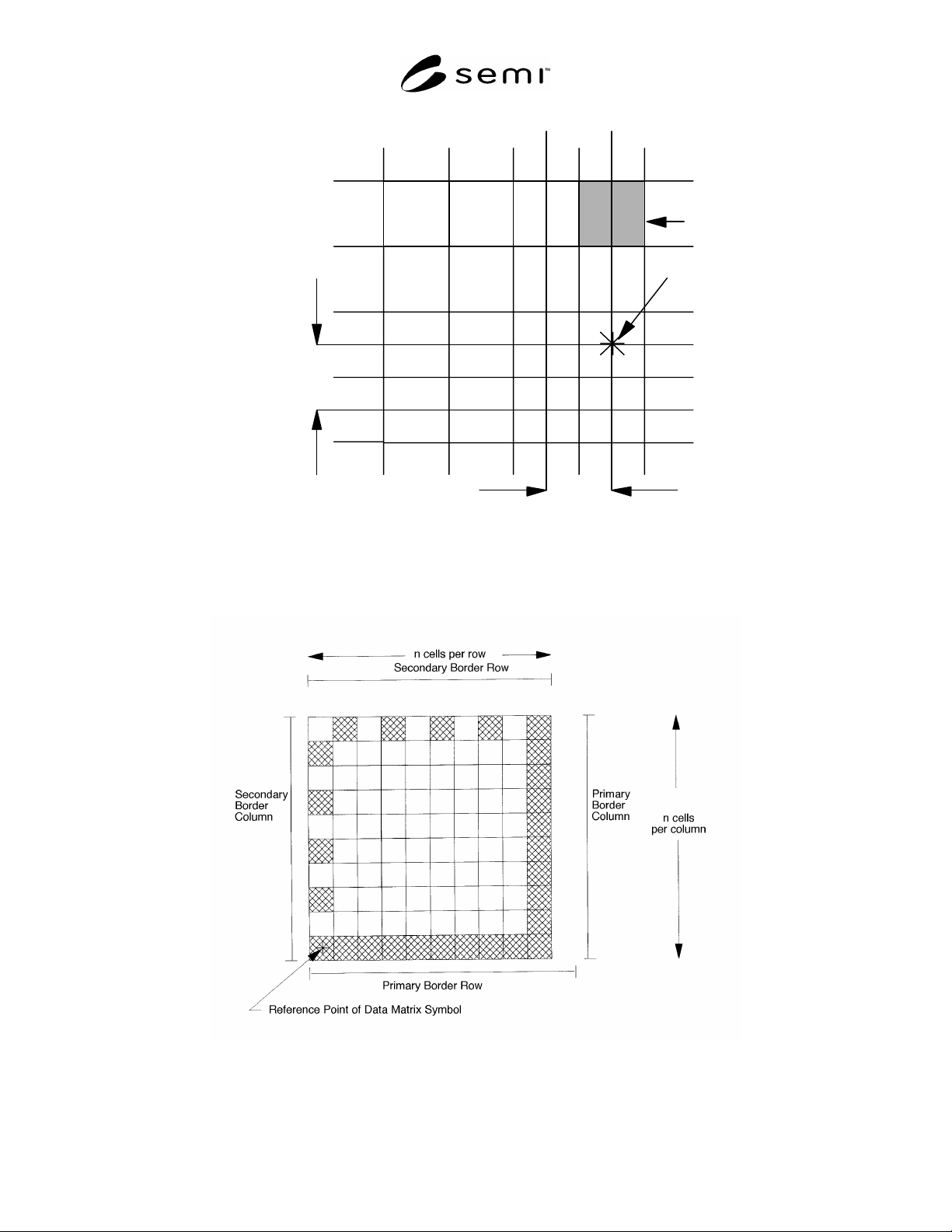
6.2 Border Rows and Columns (see Figure 3)
6.2.1 One border row and one border column shall
contain a dot in each cell. These are identified as the
primary border row and the primary border column.
These are used by the code reader to determine the
reference point and orientation of the matrix.
6.2.2 The opposing (secondary) border row and
column shall contain dots in alternating cells.
6.2.3 The reference point of the symbol shall be the
physical centerpoint of the cell common to the primary
border row and the secondary border column.
6.2.4 The maximum dot misalignment within a cell is
20 µm. This ensures that a minimum size dot covers a
cell central area of radius 25 µm (see Figure 4).
SEMI T2-0298 © SEMI 1993, 2004 2
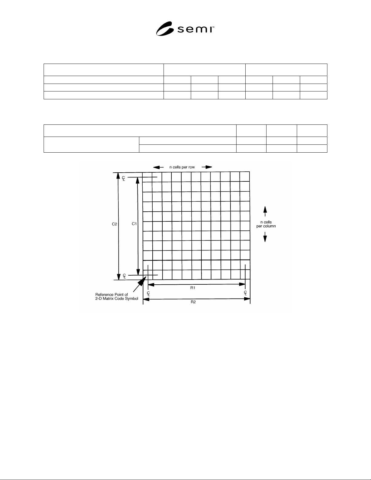
Table 1 Matrix Code Symbol Dimensions
Square Arrays for Use on 125 to 200 mm Wafers C
1
, R
1
(µm)
#1
C
2
, R
2
(µm)
#1
# of cells in row or column 16 18 20 16 18 20
125 µm spacing 1875 2125 2375 2000 2250 2500
150 µm 2250 2550 2850 2400 2700 3000
#1: See Figure 1 for pictorial representation of Dimensions C
1
, C
2
, R
1
, and R
2
.
Table 2 Message Character Count in Square Arrays for Use on 125 to 200 mm Wafers
# of Cells in a Row or Column 16 18 20
8-bit 10 16 20 Maximum # of Message Characters
Mostly upper-case 16 25 31
Figure 1
Data Matrix Field Dimensions
SEMI T2-0298 © SEMI 1993, 2004 3
Cell
Cell Center
Row
Column
C
L
C
L
S
S
S = 125 or 150 um, center to center
Figure 2
Data Matrix Cell Spacing
Figure 3
Border Rows and Columns: ECC200
SEMI T2-0298 © SEMI 1993, 2004 4