semi合集-English.pdf - 第3297页
SEMI E130-1104 © SEMI 2003, 2004 11 17.2.3 The Z coordin ate is zero if t he wafer is out of cont act (the chuck i s down) wi th the prob es and one if it is in contact (the c huck is up ). 17.2.4 The MOVE command specif…

SEMI E130-1104 © SEMI 2003, 2004 10
a description of suspending substrates). A substrate
that was suspended will already be in the IN PROCESS
state.
17.1.4 Unloading Substrates
17.1.4.1 LOAD-SUBSTRATE Command — When the
host issues the LOAD-SUBSTRATE command, the
substrate currently occupying the chuck is removed
from the chuck and placed in the destination substrate
location (This assumes that no additional post-chuck
substrate locations exist). The substrate state model
transitions from the IN PROCESS to PROCESSED
state. When the substrate is loaded in its destination
substrate location, the substrate transitions from the AT
WORK to the AT DESTINATION state.
17.1.4.2 UNLOAD-SUBSTRATE Command — The
host issues the UNLOAD-SUBSTRATE command to
remove the substrate from the chuck and place it in its
destination substrate location leaving the chuck
unoccupied. For pipelined configurations, the
substrate(s) in the pipeline remain in their current
location. The state model for the substrate removed
from the chuck transitions from the IN PROCESS to
PROCESSED state. When the substrate is loaded in its
destination substrate location, the substrate transitions
from the AT WORK to the AT DESTINATION state.
This command cannot be used to suspend the substrate
occupying the chuck.
17.1.4.3 UNLOAD-ALLSUBSTRATES Command —
The host issues the UNLOAD-ALLSUBSTRATES
command to return all substrates occupying the chuck
and pipeline stages to their respective carriers. For
pipelined configurations, substrates occupying a pre-
chuck pipeline stage are returned to their source
substrate location. The state model for these substrates
transitions from the AT WORK to AT SOURCE state
while remaining in the NEEDS PROCESSING state.
17.1.4.3.1 UNLOAD-ALLSUBSTRATES with
SUSPEND — If the host intends to continue processing
the substrate occupying the chuck, the host includes the
SUSPEND parameter with the UNLOAD-
ALLSUBSTRATES command. (See Section 17.1.5
for a description of suspending substrates.)
17.1.4.3.2 UNLOAD-ALLSUBSTRATES no SUSPEND
— If the host has completed processing the substrate
occupying the chuck, the host issues the UNLOAD-
ALLSUBSTRATES without the SUSPEND parameter.
The substrate occupying the chuck transitions from the
IN PROCESS to PROCESSED state and is delivered to
the destination substrate location. When the substrate is
loaded in the destination substrate location, the
substrate transitions from the AT WORK to the AT
DESTINATION state.
17.1.5 Suspending Substrates
NOTE 6: Substrate Suspending and Resuming are not Job
Control collection events (e.g. CJ/PJ PAUSE/RESUME). A
substrate can be suspended as part of a normal process
interrupt to allow a service task to be performed as directed
by the host.
17.1.5.1 The host can suspend processing on a
substrate in order to free the chuck for other purposes
such as performing diagnostics or maintenance. A
suspended substrate will be returned to its source
substrate location and remains in the IN PROCESS
state. When the substrate is loaded into the source
substrate location, the substrate transitions from the AT
WORK to the AT SOURCE state.
17.1.5.2 Suspending a substrate does not change the
order in which substrates are processed within a Process
Job.
17.1.5.3 The commands that result in a substrate being
suspended are: UNLOAD-ALLSUBSTRATES with
SUSPEND and LOAD-TEST-SUBSTRATE. It is
expected that additional capabilities may exist that
result in a substrate being suspended (such as cleaning
probes with a cleaning disk).
17.1.6 Resuming a Suspended Substrate
17.1.6.1 A substrate that has been suspended will be
the first substrate loaded onto the chuck when
processing resumes.
17.1.6.2 If a substrate was suspended automatically as
part of a service task, the equipment will automatically
resume the suspended substrate prior to indicating that
the service task has completed.
17.1.6.3 If the host suspended a substrate by issuing
the UNLOAD-ALLSUBSTRATES with SUSPEND,
the host resumes the suspended substrate by issuing the
LOAD-SUBSTRATE command.
17.2 Chuck Movement (Intra-Substrate Moves)
17.2.1 When a control map is used to specify stepping,
the INDEX Remote command must be used to move to
the next die location. When a control map is not used,
either the MOVE, MOVE-ABS or MOVE-SUBSTEP
Remote commands must be used to specify motion.
17.2.2 Die coordinates are row and column numbers.
Moving the wafer one row increases or decreases the
DieYCoordinate by one. Moving the wafer one column
increases or decreases the DieXCoordinate by one.
Following an INDEX command the die coordinates can
be retrieved from the variables “DieXCoordinate” and
“DieYCoordinate”.
SEMI E130-1104 © SEMI 2003, 2004 11
17.2.3 The Z coordinate is zero if the wafer is out of contact (the chuck is down) with the probes and one if it is in
contact (the chuck is up).
17.2.4 The MOVE command specifies the number of rows and columns to move from the current position. When
the move is complete, DieXCoordinate will be changed to DieXCoordinate+X; DieYCoordinate will be changed to
DieYCoordinate+Y. When the Z parameter is included in the MOVE command, a value of (Z = –1) moves the
chuck to the down coordinate, a value of (Z = +1) moves the chuck to the up coordinate, and a value of (Z = 0)
leaves the chuck in the starting Z coordinate.
17.2.5 The MOVE-ABS command specifies the new die coordinates. When the move is complete, DieXCoordinate
will be changed to X; DieYCoordinate will be changed to Y; and the chuck will be down (Z = 0) or up (Z = 1).
17.2.6 The MOVE-SUBSTEP remote command moves the substrate in units smaller than the die size. The step
resolution for the X,Y and Z axis is available for query from the equipment status variables MinXStep, MinYStep
and MinZStep. X, Y, and Z are all relative motions in the specified units. The prober may apply an appropriate
compensation factor to adjust for thermal expansion, etc.
18 Coordinate System
18.1 This standard provides a coordinate system capable of describing simple geometries. Additional user-defined
attributes may be required in addition to the attribute definitions contained in this specification.
18.2 This coordinate system does not include information for establishing which devices on a substrate are “good”
devices. The guidelines for assigning the row and column index number are set forth in SEMI G81.
18.3 General Coordinate Attributes
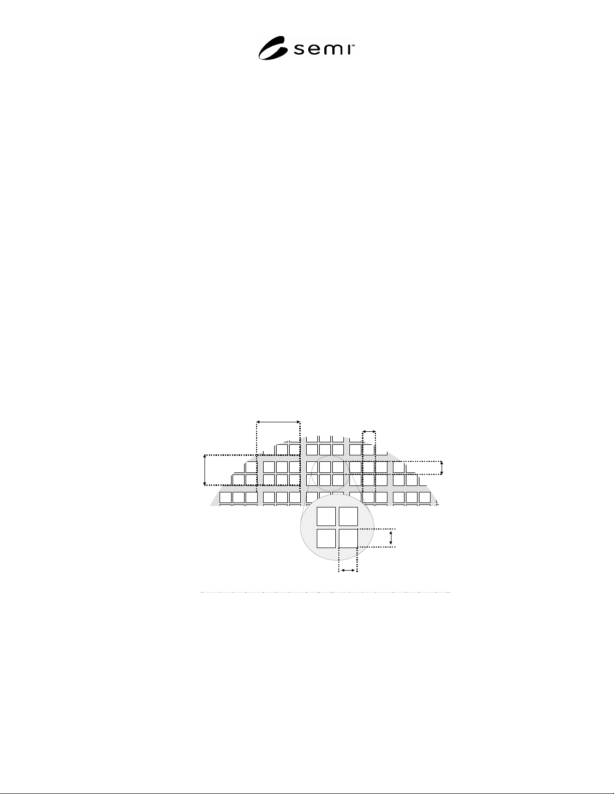
18.3.1 Rows — The number of rows on a substrate in the Y-axis. A row must contain at least one complete device
to be included in this count.
18.3.2 Columns — The number of columns on a substrate in the X-axis. A column must contain at least one
complete device to be included in this count.
MatrixSizeX
MatrixSizeY
StepSizeX
StepSizeY
DeviceSizeY
DeviceSizeX
Figure 3
Dimensional Attributes
18.4 Matrix Substrates
18.4.1 The term “Matrix” is used to describe the step periodicity associated with an exposure field. Applicable
when the step size between adjacent devices spanning an exposure field is different from the step size of adjacent
devices within an exposure field.
18.4.2 This standard does not address complex geometries where individual device sizes vary within an exposure
field or between exposure fields or where exposure step sizes vary across the substrate.
SEMI E130-1104 © SEMI 2003, 2004 12
18.4.3 A non-matrix substrate is a substrate where the step size between adjacent devices spanning an exposure
field is no different from the step size between adjacent devices within an exposure field.
18.4.4 Matrix Attributes
18.4.4.1 MatrixDeviceRows — This is the number of device rows within an exposure field. This value is dependent
upon the Orientation recipe attribute but not the OrientationOnChuck attribute. For non-matrix substrates, the value
of this attribute is 1.
18.4.4.2 MatrixDeviceCols — This is the number of device columns within an exposure field. This value is
dependent upon the Orientation recipe attribute but not on the OrientationOnChuck attribute. For non-matrix
substrates, the value of this attribute is 1.
18.4.4.3 MatrixSizeX — The X-axis step size in microns between a device in one exposure field and the same
device in an adjacent exposure field. For non-matrix substrates, the value of this attribute is equal to the StepSizeX
attribute. This attribute is dependant on the Orientation recipe attribute.
18.4.4.4 MatrixSizeY — The Y-axis step size in microns between a device in one exposure field and the same
device in an adjacent exposure field. For non-matrix substrates, the value of this attribute is equal to the StepSizeY
attribute. This attribute is dependant on the Orientation recipe attribute.
18.5 Reference Device
18.5.1 The Reference Device establishes the link between the coordinate system Row and Column and the physical
location on the substrate.
18.5.2 Reference Device Attributes
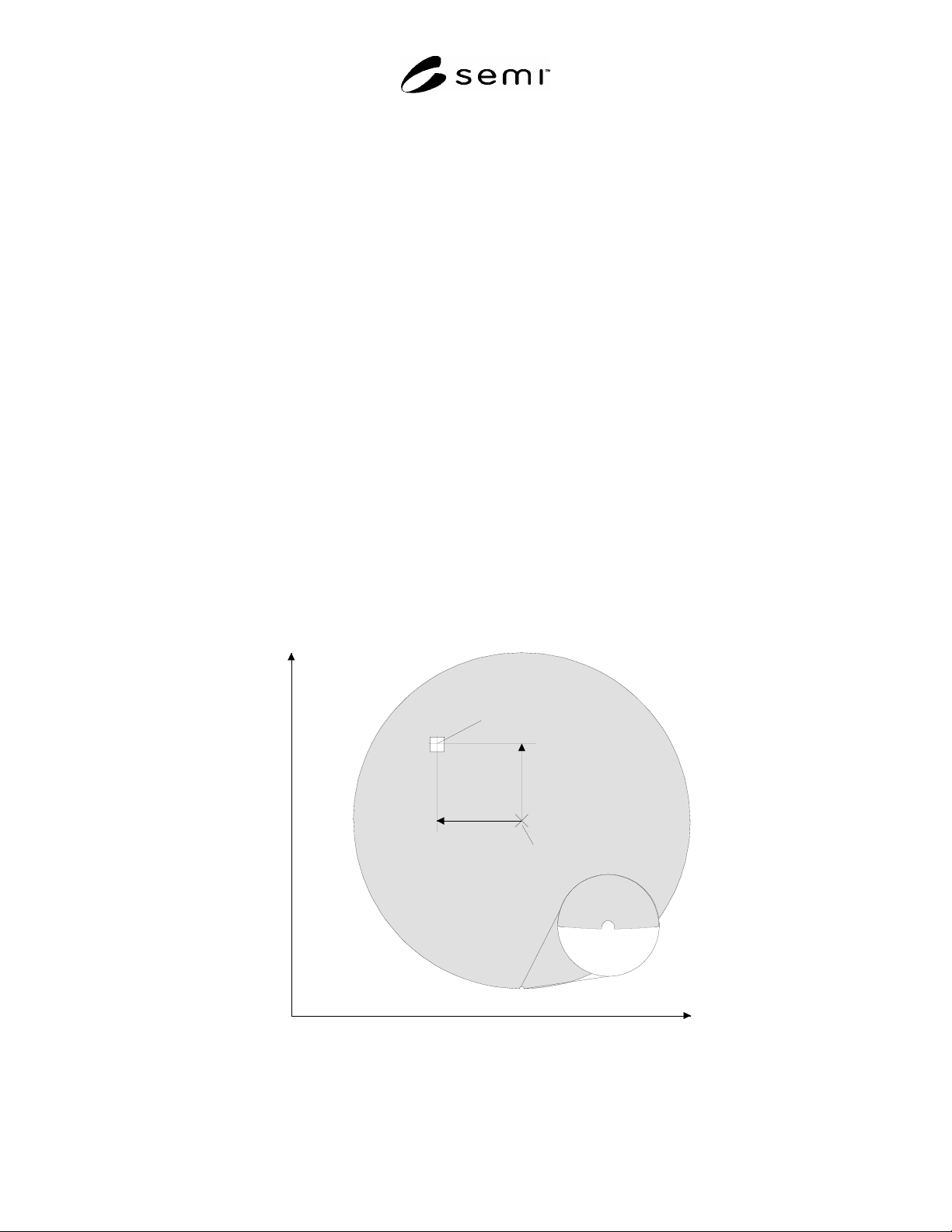
18.5.2.1 RefDevicePosX — This is the offset of the center of the reference device in the X direction from the center
of the substrate with the substrate Orientation at 0º and OriginLocation = 3.
18.5.2.2 RefDevicePosY — This is the offset of the center of the reference device in the Y direction from the center
of the substrate with the substrate Orientation at 0º and OriginLocation = 3.
y
-x
+x
+y
SUBSTRATE CENTER
REFERENCE DEVICE CENTER
Figure 4
Reference Device Position (RefDevicePosX and RefDevicePosY)