semi合集-English.pdf - 第7604页
SEMI T1-95 © SEMI 1993, 2003 5 Table 4 BC 412 Symbo l Content for Wafer Marking Position Description Modules 1 Leading Quiet Zone 10 2 Start Character 3 3 User Definable 12 4 Check Ch aracter 12 5 to (n + 2) User Definab…
SEMI T1-95 © SEMI 1993, 2003 4
Table 2 Characteristics of BC-412 Bar Code
Encodable Character Set Alphanumeric (except O) with No Non-Numeric or Non-Alphabetic Characters (see Table 3)
Code Type Continuous
Symbol Length Variable: for this application, symbol can be formed from 13.200 mm ± 0.050 mm (0.5760" ±
0.020") including the Quiet Zones, to 29.040 mm ± 0.050 mm (1.1400" ± 0.0020") including the
Quiet Zones.
Bi-Directional Decoding Yes
Number of Check Characters One
Character Self Checking Yes
Character Self Clocking Yes
Character Dimensions See Table 1 and Figure 1.
Non-Data Overhead Six Modules
Table 3 BC 412 Code — Character Construction and Values
Character
Module Sequence
Check Character
Value
Character
Module Sequence
Check Character
Value
0 |-|-|-|----- 00 I |--|-|----|- 27
1 |-|-|--|---- 15 J |--|--|-|--- 16
2 |-|-|---|--- 17 K |--|--|--|-- 24
3 |-|-|----|-- 29 L |--|--|---|- 04
4 |-|-|-----|- 11 M |--|---|-|-- 34
5 |-|--|-|---- 33 N |--|---|--|- 12
6 |-|--|--|--- 19 O
7 |-|--|---|-- 21 P |--|----|-|- 32
8 |-|--|----|- 08 Q |---|-|-|--- 18
9 |-|---|-|--- 02 R |---|-|--|-- 01
A |-|---|--|-- 07 S |---|-|---|- 14
B |-|---|---|- 25 T |---|--|-|-- 13
C |-|----|-|-- 20 U |---|--|--|- 26
D |-|----|--|- 22 V |---|---|-|- 05
E |-|-----|-|- 09 W |----|-|-|-- 31
F |--|-|-|---- 30 X |----|-|--|- 28
G |--|-|--|--- 03 Y |----|--|-|- 23
H |--|-|---|-- 06 Z |-----|-|-|- 10
Start |-- Stop |-|
Legend: |=one bar; -=one module blank (no bar)
SEMI T1-95 © SEMI 1993, 2003 5
Table 4 BC 412 Symbol Content for Wafer Marking
Position Description Modules
1 Leading Quiet Zone 10
2 Start Character 3
3 User Definable 12
4 Check Character 12
5 to (n + 2) User Definable 12/character
(n + 2) + 1 Stop Character 3
(n + 2) + 2 Trailing Quiet Zone 10
Total Modules including Quiet Zones f(n) = (12n) + (6) + (20)
Total Modules within Marking Area Only f(n) = (12n) + (6)
n = Number of characters in the code as defined by the user, including check character, excluding Start and Stop characters.
Table 5 Code Field Location Dimensions (see Figures 3 and 4)
Dimension Flatted Wafer (Figure 3) Flatted Wafer (Figure 3) Notched Wafer (Figure 4) Notched Wafer (Figure 4)
n = 7 n = 18 n = 7 n = 18
A 1.624 mm ± 0.025 mm same 1.624 mm ± 0.025 mm same
B
3
4.666 mm ± 0.500 mm 12.476 mm ± 0.500 mm 4.666 mm ± 0.500 mm 12.476 mm ± 0.500 mm
C
3
9.332 mm ± 0.030 mm 24.952 mm ± 0.050 mm 9.332 mm ± 0.030 mm 24.052 mm ± 0.050 mm
E
1
3.350 mm ± 0.500 mm same 7.400 mm ± 0.050 mm same
F 0.700 mm ref. same 0.700 mm ref. same
G
3
5.400 mm ± 0.500 mm 13.320 mm ± 0.500 mm 5.400 mm ± 0.500 mm 13.320 mm ± 0.500 mm
H
3
10.800 mm ± 0.050 mm 26.640 mm ± 0.050 mm 10.800 mm ± 0.050 mm 26.640 mm ± 0.050 mm
J 2.000 mm ± 0.025 mm same 2.000 mm ± 0.025 mm same
L
3
13.200 mm ± 0.050 mm 29.040 mm ± 0.050 mm 13.200 mm ± 0.050 mm 29.040 mm ± 0.050 mm
M
2
1.260 mm min. same 1.260 mm min. same
1
This dimension is the distance between the centerline of the bottom dot in the bar code and the edge of the finished wafer.
2
This dimension is the distance between the centerline of the first module of the start character (or the last element of the stop character) and the
outer edge of the Quiet Zone.
3
n = 7 and n = 18 values represent the smallest to the largest extremes of the bar code symbology to be used.
The formulas for calculating all other values in between are as follows:
Dimension (B)
(Usin
g SEMI M
12 Sizing)
=
((n
–
1) Character Spacing)
+
(Character Width)
2
=
((n – 1)
×
1.420)
+
0.812
2
±
0.500
mm = ((0.710n – 0.304)
±
0.500)
mm
D
i
mens
i
on
(
C
)
=
(((
n - 1
)
×
1.420
)
+ 0.812
±
0.050
)
mm =
((
1.420n - 0.608
)
±
0.050
)
mm
Dimension (G) =
((12n)
×
0.120) + (6
×
0.120)
2
±
0.500
mm
=
((0.720n - 0.360)
±
0.500)
mm
Dimension
(H) = ((( 12 n)
×
0 . 1 20) + ( 6
×
0 . 120 )
±
0.050)
mm = ((1.440n - 0.720)
±
0.050)
mm
Dimension
(L) = ((( 12 n)
×
0 . 1 20) + ( 6
×
0 . 120 )
±
(20
×
0.120)
±
0.050
mm = ((1.440n - 3.120)
±
0.050)
mm
Tolerance for module spacing is non - cumulative (see Table 1).
SEMI T1-95 © SEMI 1993, 2003 6
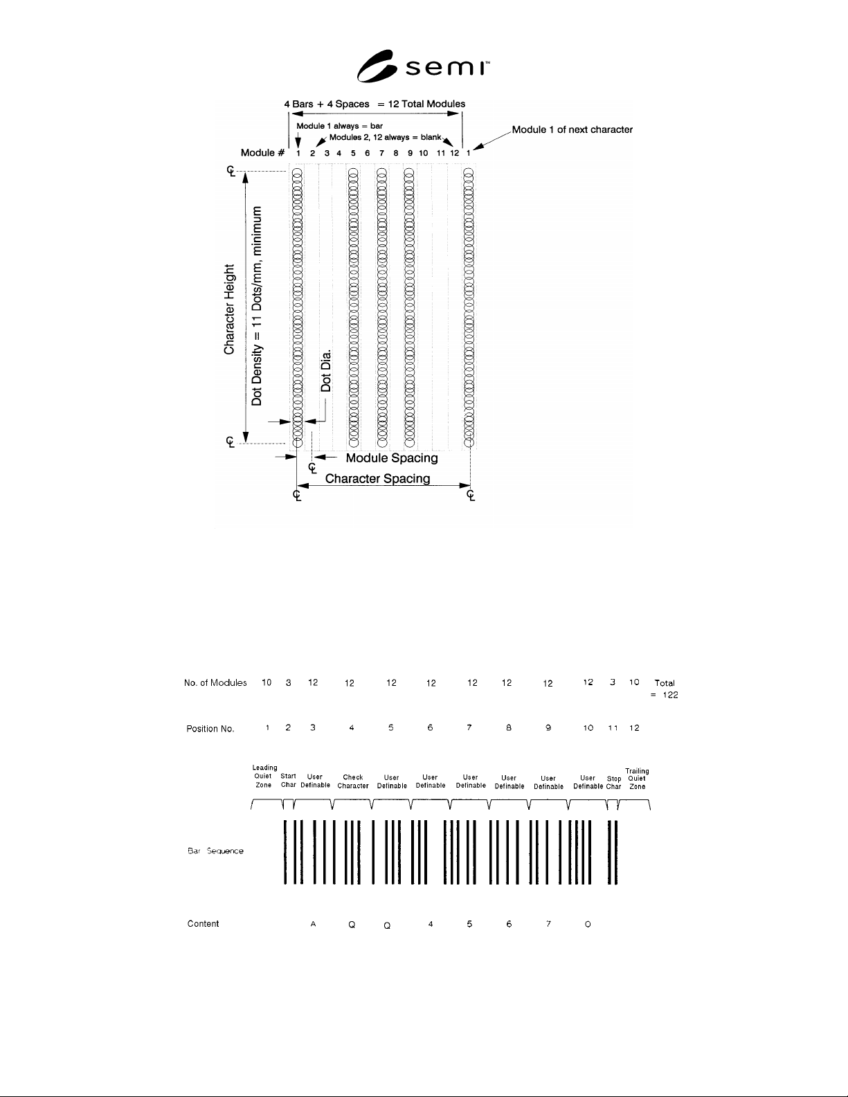
Figure 1
BC-412 Data Character Construction
NOTE 4: Each bar code character contains four bars and four spaces. A space is one or more contiguous blanks. Module 1 is
always a bar; the other three bars are distributed among modules 3−11; modules 2 and 12 are always spaces. One or more blanks
which comprise a space must occur between bars.
Figure 2
BC-412 Character Position and Module Content