semi合集-English.pdf - 第6571页
SEMI G86-0303 © SEMI 2003 3 Datum pl ane Support 5 ° Figure 3 Setting Condition of Test Specimen 7 Test Specimens 7.1 The shape and dime nsions of the te st specim ens shall be agreed between the interested parties. 7.2 …
SEMI G86-0303 © SEMI 2003 2
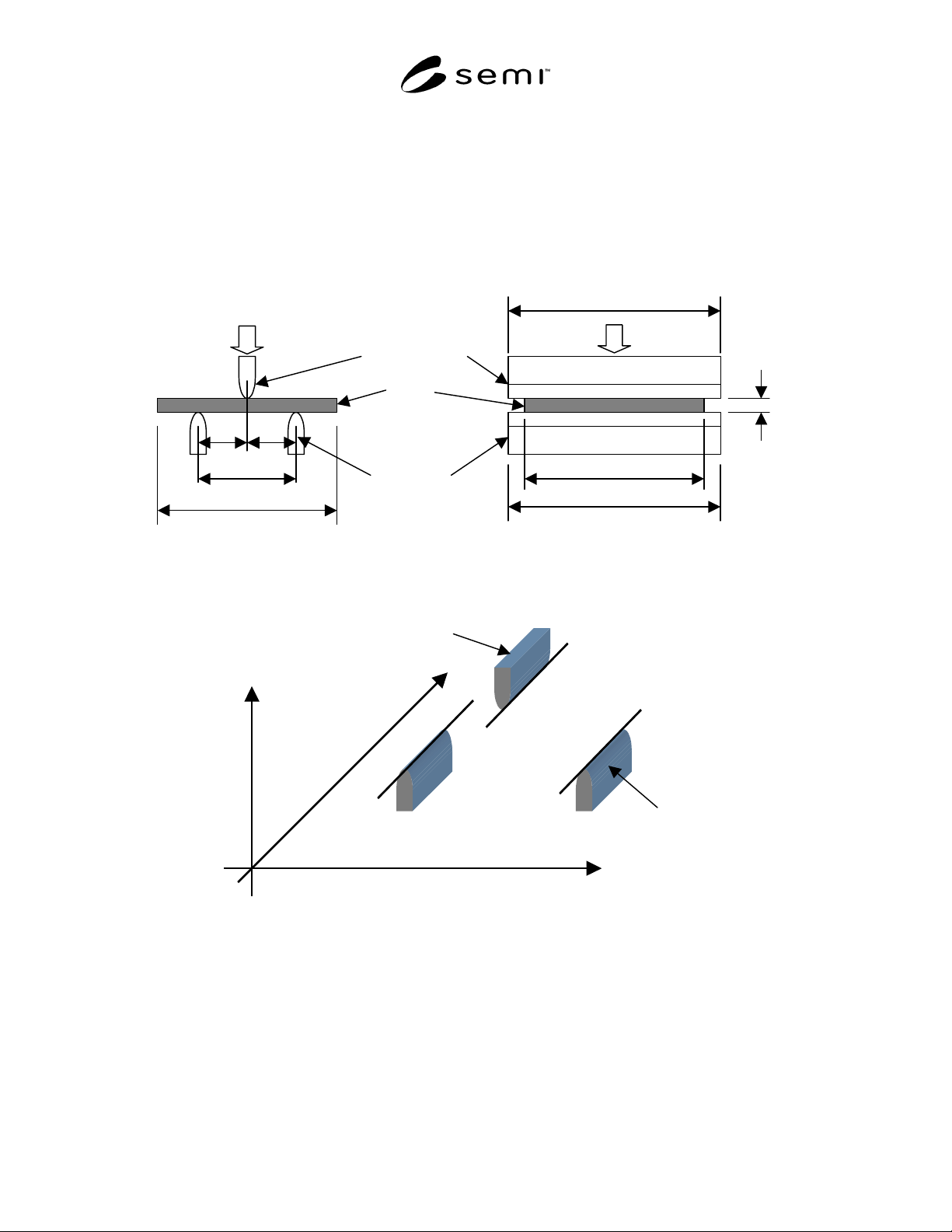
6.2.2 The radius of the supports and the loading edge
shall be 0.3 mm ± 0.02 mm.
6.2.3 The width of supports B
1
and loading edge B
2
shall be longer than the width of test specimen b.
6.2.4 Two supports shall be parallel to X direction
within ± 0.03 mm and to Z direction within ± 0.02 mm.
And two supports to the loading edge shall be parallel
to X direction within ± 0.03 mm and to Z direction
within ± 0.02 mm (see Figure 2).
6.2.5 The tip of the supports and loading edge shall be
hardened more than HRc60 specified in ISO/DIS 6508-
1.
6.2.6 The tip of the supports and loading edge shall
have the roughness less than 1.6 umRa specified in ISO
468.
Unit: mm
B
1
L
/2
L
/2
L
h
b
P
w
P
Loading edge
Supports
Test
specimen
B
2
Figure 1
Position of Test Specimen at Start of Test
Y
X
Loading edge
Support
Z
Figure 2
Arrangement of Supports and Loading Edge
SEMI G86-0303 © SEMI 2003 3
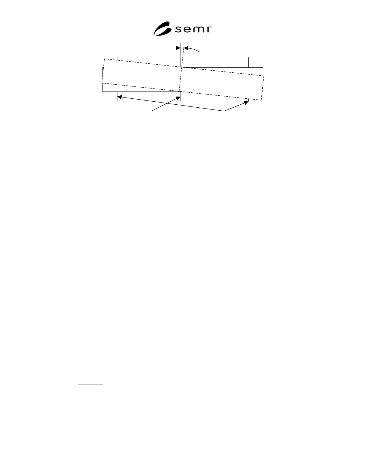
Datum plane Support
5 °
Figure 3
Setting Condition of Test Specimen
7 Test Specimens
7.1 The shape and dimensions of the test specimens
shall be agreed between the interested parties.
7.2 Test specimen shall be Silicon Die.
7.3 At least 25 test specimens shall be pulled from a
wafer.
8 Procedure
8.1 Measure the thickness h, width b, and length w.
The accuracy of h and b shall be within ± 5%.
8.2 Adjust the span L in accordance with the following
conditions,
at h < 0.1 mm : L ≤ 2 mm and L ≤ 50 h
at h ≥ 0.1 mm : 2 mm ≤ L and L ≤ 20 h
8.3 Place the test specimen on the two supports within
± 5° of the deviation from datum plane (see Figure 3).
The evaluated surface shall be applied the tensile force.
8.4 Set the test speed less than 5 mm/min in order to
avoid the impact on test specimen and apply the force at
midspan.
8.5 Record the force of the specimen at the break.
9 Calculation
9.1 Flexural Stress — Calculate the flexural stress
parameters defined in Section 4 using the following
equation:
(1)
σ
fB
=
3
P
B
L
2
bh
2
Where:
σ
fB
is the flexural stress at break in question (Mpa);
P
B
is the applied force at break, in newtons (N);
L is the span, in millimeters (mm);
b is the width, in millimeters (mm), of the test
specimen; and
h is the thickness, in millimeters (mm), of the test
specimen.
NOTE 5: Equation (1) can only be used for test specimens
with linear stress/strain behavior.
10 Test Report
10.1 The test report shall include the following
information:
• the directions major axes of the specimens if test
specimen has,
• the evaluated surface,
• the dimensions of the test specimens (thickness h,
width b, length w),
• the nominal span length used,
• the number of specimens tested,
• the speed of testing,
• the individual test results, the flexural stress at
break, and
• the date of the test.
SEMI G86-0303 © SEMI 2003 4
NOTICE: SEMI makes no warranties or
representations as to the suitability of the standards set
forth herein for any particular application. The
determination of the suitability of the standard is solely
the responsibility of the user. Users are cautioned to
refer to manufacturer's instructions, product labels,
product data sheets, and other relevant literature,
respecting any materials or equipment mentioned
herein. These standards are subject to change without
notice.
By publication of this standard, Semiconductor
Equipment and Materials International (SEMI) takes no
position respecting the validity of any patent rights or
copyrights asserted in connection with any items
mentioned in this standard. Users of this standard are
expressly advised that determination of any such patent
rights or copyrights, and the risk of infringement of
such rights are entirely their own responsibility.