semi合集-English.pdf - 第2929页
SEMI E109-0305 © SEMI 2001, 2005 39 Verification Method Desired Host Actions before Load Equipment Action When Reticle Pod Is Loaded Equipment Action when Ret icle is removed from cass ette Host Actions after Load Verifi…
SEMI E109-0305 © SEMI 2001, 2005 38
Verification
Method
Desired
Host Actions before
Load
Equipment Action When
Reticle Pod Is Loaded
Equipment Action when Reticle is
removed from cassette
Host Actions after Load
Verification Failed: The
equipment initiates Transition
12, the Transition 22 of the
reticle state model the reticle
object created via the service is
destroyed. For the reticle object
created via the reticle ID read
(the “unexpected reticle”) the
reticle is instantiated via
Transition 7 into the RETICLE
WAITING FOR HOST state.
Verification Failed: The
host uses either the
RejectReticle service to
indicate that the equipment
should not use the reticle for
processing, or indicates to
the production equipment
that it may proceed with the
unexpected reticle, by
sending the
ProceedWithReticle service.
In both cases the ReticleID
specified in the service is
equal to the one determined
by the ReticleID read.
Host Based None required, the
host may issue a
ReserveAtPort
service.
The production
equipment reads the
PodID and reports it to
the host in an event
report. Following PodID
read the equipment
initiates Transition 3 of
the Reticle Pod State
Model and a reticle pod
object with the PodID
equal to the one
determined by the PodID
read is instantiated. The
reticle
pod shall not be
opened by the equipment
until and unless the
ProceedWithPod service
is received from the host.
The production equipment reads
the ReticleID and reports it to
the host in an event report.
Following the ReticleID read the
equipment initiates Transition 5
(if a particle inspection is
required, but reticle ID
verification is not) or Transition
6 (if neither a reticle ID
verification nor a particle
inspection is required), or
Transition 7 (if an ID
verification is required) of the
Reticle State Model and a reticle
object determined by the
ReticleID read is instantiated.
Verification Passed: The
host sends a
ProceedWithReticle service
indicating the verification
passed. The equipment may
proceed with reticle
qualification.
Verification Failed: The
host uses the RejectReticle
service to indicate that the
equipment should not use
the reticle for processing.
ProceedWithPod
after Pod arrival,
includes Content
Map:
None
Equipment Reads the
Pod, reports ID. After
receiving
ProceedWithPod with a
ContentMap, the Reticle
is instantiated via
Transition 4.
Transition 9 of the Reticle State
model occurs. The Reticle ID is
read.
Verification Passed:
The equipment may proceed
with reticle verification.
Verification Passed:
None
SEMI E109-0305 © SEMI 2001, 2005 39
Verification
Method
Desired
Host Actions before
Load
Equipment Action When
Reticle Pod Is Loaded
Equipment Action when Reticle is
removed from cassette
Host Actions after Load
Verification Failed:
The Equipment initiates
Transition 12, then Transition 22
of the reticle state model; the
reticle created via the service is
destroyed. For the reticle
created via the ID Read (the
“unexpected reticle”), the reticle
is created via Transition 7 into
the RETICLE WAITING FOR
HOST state.
Verification Failed:
The host uses either the
RejectReticle service to
indicate that the equipment
should not use the reticle for
processing or indicates to
the equipment that it may
proceed with the unexpected
reticle, by sending the
ProceedWithReticle service.
In both cases the ReticleID
specified in the service is
equal to the one determined
by the ReticleID read.
15.5 Table 18 clarifies the relation of the reservation and verification to the related services.
Table 18 Reservation and Verification Relation to Service
Information Provided with Service Reser-
vation
PodID
Verification
Cassette
SlotMap
Verification
ReticleID
Verification
Service Used
Port ID PodI
D
SlotMa
p
Content
Map and
ReticleID
1 Yes Equipment
based
Equipment
based
Equipment
based
Bind, or
ReticleTransferJob
Yes Yes Yes Yes
2 Yes Equipment
based
Host based Host based Bind Yes Yes No No
3 Yes Host based Host based Host based ReserveAtPort Yes No No No
ProceedWithPod
(following ID read and
host verification)
No Yes No No
4 Yes Host based Equipment
based
Host based ReserveAtPort Yes No No No
ProceedWithPod to
provide slotmap
(following ID read and
host verification)
No Yes Yes No
5 No Equipment
based
Equipment
based
Equipment
based
PodNotification No Yes Yes Yes
6 No Equipment
based
Host based Host based PodNotification No Yes No No
7 No Host based Equipment
based
Host based ProceedWithPod to
provide slotmap
(following ID read and
host verification)
No Yes Yes No
8 No Host based Host based ProceedWithPod
(following ID read and
host verification)
No Yes No
SEMI E109-0305 © SEMI 2001, 2005 40
16 Reticle Pod Release Control
16.1 For equipment, where Pod Read/Write technology is used and the Host initiates writing, the reticle pod or
reticle cassette must remain at the write position where the tag may be accurately written on until the Host has
completed its entire read and write operations. For this purpose, a variable that affects the equipment releasing a
pod is defined.
16.2 Pod Hold Trigger — Equipment shall allow the user to select a trigger to release the carrier pod when
reading/writing is complete. Release does not mean the equipment must move the pod from the location it currently
occupies, only that it is permissible to do so.
16.2.1 Pod Hold Trigger set to Host Release — If the Pod Hold trigger is set to Host Release, equipment shall hold
the pod at the write position until the PodRelease service is received.
16.2.2 PodHold Trigger set to Equipment Release — If the Pod Hold trigger is set to Equipment Release, the
equipment shall release the reticle pod based on the when the equipment has finished removing all reticles from the
pod, finished placing all reticles in the pod, and in the case where the equipment initiates writing until the equipment
has finished writing.
16.3 Fixed Buffer Equipment shall allow the user to select a trigger to unclamp the reticle pod based on AMHS
arrival at the equipment. If the access mode is MANUAL, the unclamp control trigger has no effect.
16.3.1 UnclampControl trigger set to PODCOMPLETE Triggered Unclamp
— The equipment automatically
unclamps the reticle pod when the reticle
pod status is COMPLETE.
16.3.2 UnclampControl trigger set to AMHS Triggered Unclamp
— The equipment behavior depends upon the
Reticle Load Port Access State. If the Reticle Pod Load port Access State is AUTO, the reticle pod remains
clamped until AMHS has arrived. The AMHS arrives and begins a PIO unload sequence.
17 Reticle Location Object Definition
17.1 A Reticle Location Object (RLO) provides a model for identifying reticle locations. Each RLO on an
equipment is assigned a reticle location ID to uniquely identify it. The assignment shall be documented by the
equipment supplier. There are two types of substrate locations: reticle pod reticle location, which is the location or
position (e.g., slot) in the reticle pod, and equipment reticle location, which is on the equipment resource. The
equipment reticle location is a persistent object, while the reticle pod reticle locations are dynamic objects that shall
be created or deleted by the placement or removal of reticle pods on the equipment. The intent is to follow E90 in
regards to location object management. The reticle location object is a subtype of the substrate location object.
17.1.1 Source reticle locations and Destination reticle locations are the points at which reticles transfer to/from the
equipment’s internal reticle locations (often locations at which processing occurs). A reticle pod reticle location is
the Source or Destination reticle location when a pod is used to transfer the reticle. An equipment reticle location
can be the Source or Destination reticle location when the reticle is transferred directly (without a pod).
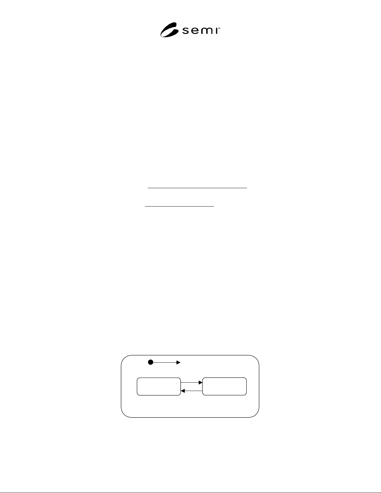
17.2 Reticle Location State Model Figure 9 below shows the dynamic behavior of the reticle location using the
Harel state chart representation.
UNOCCUPIED OCCUPIED
RETICLE LOCATION
1
2
Figure 9
Reticle Location State Model Diagram