semi合集-English.pdf - 第3293页
SEMI E130-1104 © SEMI 2003, 2004 7 9 Related Standards Hierar ch y 30 0mm Stand ar d s ( E 4 0 , E8 7 , E9 0 , E9 4 ) SE M I E 30 ( G E M ) SE M I E 5 ( SE CS - II ) P S E M 30 0 (t hi s sp e c i f i cat i o n ) P r o v …

SEMI E130-1104 © SEMI 2003, 2004 6
#. Current State Trigger New State Action Comment
10 AWAITING
COMMAND
The prober receives a
motion related remote
command.
MOVING XYZ The prober moves the
main chuck to the
specified location on the
substrate.
See Section 17 for a
description of the motion
related commands the host
can issue to trigger this
transition.
See the Collection Event
Table Section 19.2 for the
list of required data items
associated with this
transition.
11 MOVING XYZ The prober has completed
the motion related task and
waits for further instructions
from the host.
AWAITING
COMMAND
Prober waits for further
instructions from the host.
12 AWAITING
COMMAND
The prober received a
remote command specifying
a service task.
SERVICE TASK See Section 16 for a
description of the prober
actions related to
performing a service task.
13 SERVICE
TASK
The prober has completed a
service task.
AWAITING
COMMAND
Prober waits for further
instructions from the host.
14 SERVICE
TASK
The prober is configured to
perform a subsequent
service task upon
completing a current service
task.
SERVICE TASK See Section 16 for a
description of the prober
actions related to
performing a service task.
Example: The recipe may
call for a probe card
inspection to automatically
follow a probe clean service
task.
15 PROCESS The processing resource has
become unavailable.
PROCESSING
BLOCKED
No further processing is
possible.
The cause of this trigger can
be an internal interrupt or an
external command from the
operator or host.
16 PROCESSING
BLOCKED
The processing resource has
become available or the
prober is handling material
in the process of terminating
a job.
PROCESS Sub-
state
See Section 8.1.7 for the
conditional return state.
If the job(s) have been
terminated, the HANDLING
MATERIAL state will be
occupied while the material
is being removed from the
prober.
17 IDLE An alarm state is entered
that causes the processing
resource to be unavailable
for processing.
IDLE WITH
ALARMS
18 IDLE WITH
ALARMS
The alarm condition has
been cleared.
IDLE
8.1.7 Process Model Conditional Table
Table 2 Process Model Conditional Table
Conditions Next State
The current Process Job is terminating HANDLING MATERIAL
The processing resource has become available and the current
Process Job remains active
Previous EXECUTING state
SEMI E130-1104 © SEMI 2003, 2004 7
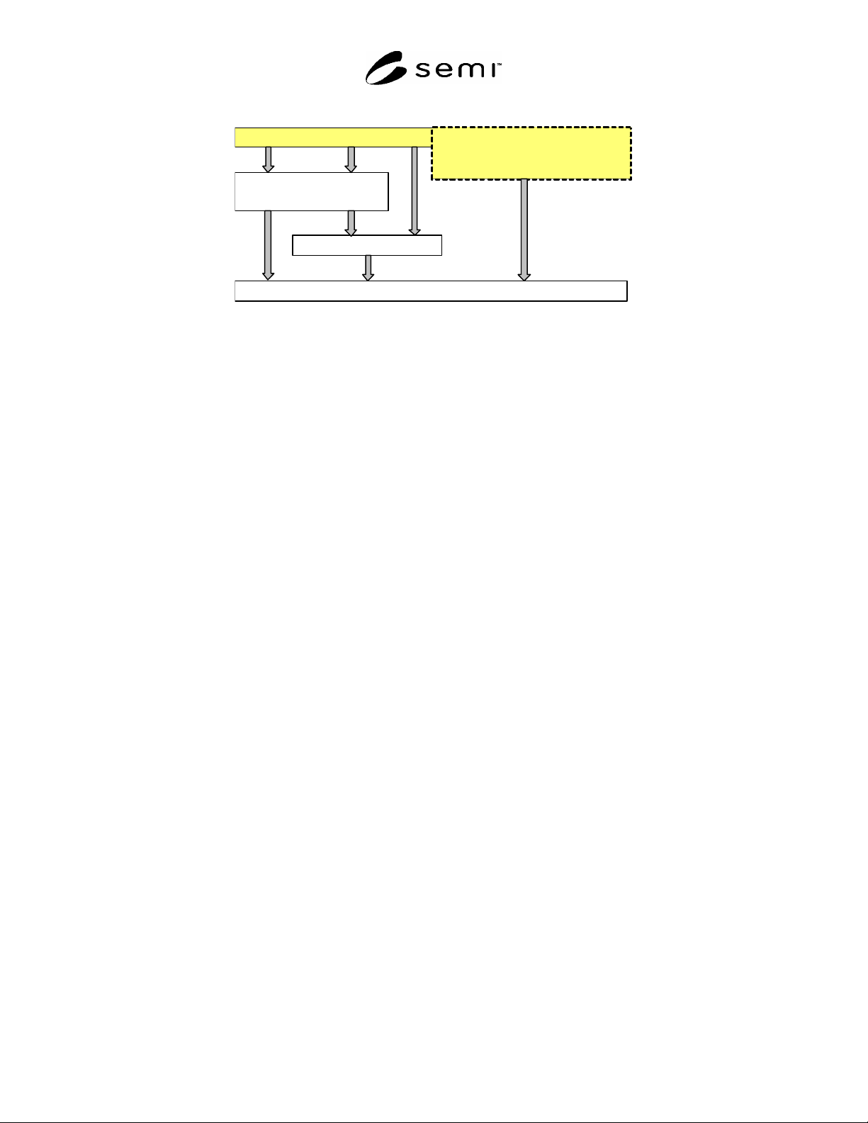
9 Related Standards Hierarchy
300mm Standards
(E40,E87,E90,E94)
SEMI E30 (GEM)
SEMI E5 (SECS-II)
PSEM300 (this specification) Provisional Specification f or
SECS-II Protocol for PSEM300
(
future document
)
Figure 2
Related Standards Hierarchy
9.1 SEMI E30 Relationship — This document does not
attempt to redefine the concepts and behaviors of SEMI
E30 (GEM). Instead, this document takes an
hierarchical approach to identifying the methods for
achieving a given task as shown in
Related Standards Hierarchy.
9.1.1 SEMI E30 Inclusions — All of the SEMI E30
state models are required with exception of the
processing state diagram. This diagram is replaced
with the one defined in this standard.
9.1.2 SEMI E30 Exclusions — Data Type restrictions
may conflict with the newer 300 mm standards and
therefore, the constraints found within the newer
standards shall take precedence over the restrictions
found in SEMI E30 section 5 “Data Types”.
10 Process Jobs
NOTE 1: SEMI E40 is required for PSEM300 compliance.
10.1 A PSEM300 prober is not able to operate as an
independent processing agent. It requires a host to
coordinate interaction with the tester. This document
defines a suitable GEM interface consisting of the
Process State Model and associated remote commands
to allow the host to act as the processing agent on
behalf of the prober to complete the execution of the
process job.
10.2 This standard assumes that if the equipment has a
pipeline (e.g. pre-align stage and main chuck), the
equipment will support concurrent process jobs such
that when the last substrate of an active process job
leaves the first pipeline stage, the equipment will
launch another process job thus maintaining continuous
material flow.
10.3 Process Job Preconditioning — This standard
does not attempt to define the set of recipe attributes
that, when different from the current equipment
configuration, will require a transition to the Process
Job SETTING UP state (preconditioning required).
The recipe attributes that do impact the Process Job
transition to SETTING UP will be user defined and
documented as such.
10.4 A PM compliance checklist must be filled out to
indicate the level of compliance to both the
Fundamental and Additional PM capabilities.
11 Control Job
NOTE 2: SEMI E94 is required for PSEM300 compliance.
11.1 See SEMI E94 for details of Control Job
management.
11.2 A substrate’s destination substrate location is
specified in the Control Job’s MtrlOutSpec attribute. If
the MtrlOutSpec attribute is not set, the destination
substrate location defaults to the source substrate
location.
11.3 A CJM compliance checklist must be filled out to
indicate the level of compliance to Fundamental CJM
capabilities (no Additional capabilities are defined at
this time).
12 Carrier Management
NOTE 3: SEMI E87 is required for PSEM300 compliance.
12.1 CarrierReCreate — After processing material for
a given carrier, the host must be able to define a new
CJ/PJ for the same carrier without having to remove the
carrier from the tool. For this, the equipment must
support the CarrierReCreate service.
12.2 A CMS compliance checklist must be filled out to
indicate the level of support for CMS for a given
equipment configuration.
13 Substrate Tracking
NOTE 4: SEMI E90 is required for PSEM300 compliance.

SEMI E130-1104 © SEMI 2003, 2004 8
13.1 Substrate Tracking must be supported for all
product substrates and substrate locations where
product substrates may reside. Some of the substrate
locations that might exist include: handling robot, post-
chuck substrate location.
13.2 The supplier may choose not to support substrate
tracking for certain internal substrate locations. This is
allowable if the substrate location will not be occupied
by product substrates (e.g. Cleaning Media tray, AUX
Tray). The supplier must document which substrate
locations are available for substrate tracking.
13.3 A CMS “CarrierReCreate” service will cause each
of the substrates contained within a recreated carrier to
be reset to the AT SOURCE and NEEDS
PROCESSING state.
NOTE 5: A STS compliance checklist must be filled out to
indicate the level of compliance to STS Fundamental and
Additional capabilities.
14 Equipment Configuration
14.1 This standard does not attempt to specify the
physical equipment configuration. The intent of this
standard is to provide a generalized specification that
applies to all configurations. The supplier is
responsible for assuring that additional features
integrate consistently with the relevant standards
impacted by the feature. The purpose of this section is
to add clarification to baseline assumptions that are
implied throughout this specification.
14.2 Pipeline
14.2.1 A typical pipeline configuration consists of a
pre-align stage used to pre-process a substrate before
loading onto the chuck. The equipment can begin
processing the substrate on the chuck while the next
substrate is being prepared on the pre-align stage. For
this configuration, the material flow is assumed to
follow the path: source substrate location pre-align
stage chuck destination substrate location. There
may be additional substrate locations both before and
after the chuck.
15 Control Maps
15.1 Control Maps provide a mechanism for
communicating the selective sites for processing in a
pre-determined manner. Control Maps are not suitable
for adaptive test where dynamic site selection is used.
15.2 Control Map Uses
15.2.1 Inking — The host can download a control map
containing the sites to be inked. The host issues the
INK DIE remote command specifying the control map
as the source for the die list.
15.2.2 Normal Processing — When using a Control
Map, the host issues the INDEX remote command to
move the prober coordinates to the next site listed in the
Control Map. The host may issue a move related
command other than INDEX to move the chuck to any
location on the substrate. Move commands other than
INDEX, do not impact the state of the Control Map.
The prober processes subsequent INDEX commands by
going to the next site listed in the Control Map. If the
Control Map does not contain additional sites the
equipment sends an event to the host indicating that the
control map has been completed.
15.2.3 Interrupted Processing — If the processing of a
substrate using a Control Map is interrupted (i.e.
Correlation Test, Probe Cleaning with a cleaning
substrate, Chuck Reset, etc...), the equipment shall
resume processing with the Control Map from the point
where processing was suspended when the substrate
processing resumes. The exceptions to this requirement
are
15.2.3.1 If the current Process Job is altered such that
the suspended substrate is no longer in the IN
PROCESS state, the Control Map is no longer valid.
15.2.3.2 If the host issues a RESET-CONTROL-MAP
command, the Control Map will resume at the first site.
If the host designates coordinates with the RESET-
CONTROL-MAP command, the prober will resume the
Control Map with the designated coordinates. It is the
responsibility of the host to assure that the coordinates
provided with this command are contained in the
Control Map.
15.3 If the host issues a SET-CONTROL-MAP
command, the prober will begin processing the Control
Map at the first site of the designated Control Map. If
the host designates coordinates with the SET-
CONTROL-MAP command, the prober will process
the Control Map beginning with the designated
coordinates. It is the responsibility of the host to assure
that the coordinates provided with this command are
contained in the Control Map.
15.4 Control Map Transmission — The method for
downloading/uploading control maps is outside the
scope of this document.
15.5 Control Map Structure — The structure of the
control map is outside the scope of this document. The
use of SEMI G81 or SEMI G85 standards is
recommended to describe map structures.
15.6 Control Map Modifications — The option to
update a control map to register sites as they are
processed is a user specific detail. In the event that
control maps are modified on the prober, the prober
must support uploading the modified maps to the host.