semi合集-English.pdf - 第4456页
SEMI D15-1296 © SEMI 1996, 2003 1 SEMI D15-1296 (Reapproved 0703) FPD GLASS SUBSTRATE SURFAC E WAVINESS MEASUREMENT METHOD This method was technically approved b y the Global Flat Panel Display Committee and is the direc…
3 SEMI D13-1101 © SEMI 1995, 2001
8.8 reflectance non-uniformity — Variation in
reflectance of the surface of color filter within the
quality area.
8.9 hill — A gently sloping projection smaller than the
cell gap width. Will cause cell gap defect.
8.10 stain — A small-area spot, with no appreciable
thickness, on the surface of some color filter material.
It may be caused by introduction of foreign substances
during processing.
8.11 layer particle — A three-dimensional substance
adhered to the surface of some color filter layer
material.
8.12 protrusion
A large, severe projection larger
than the cell gap width. Will cause cell gap defect.
‚ q ‚ f ‚ a ‚ q ‚ f
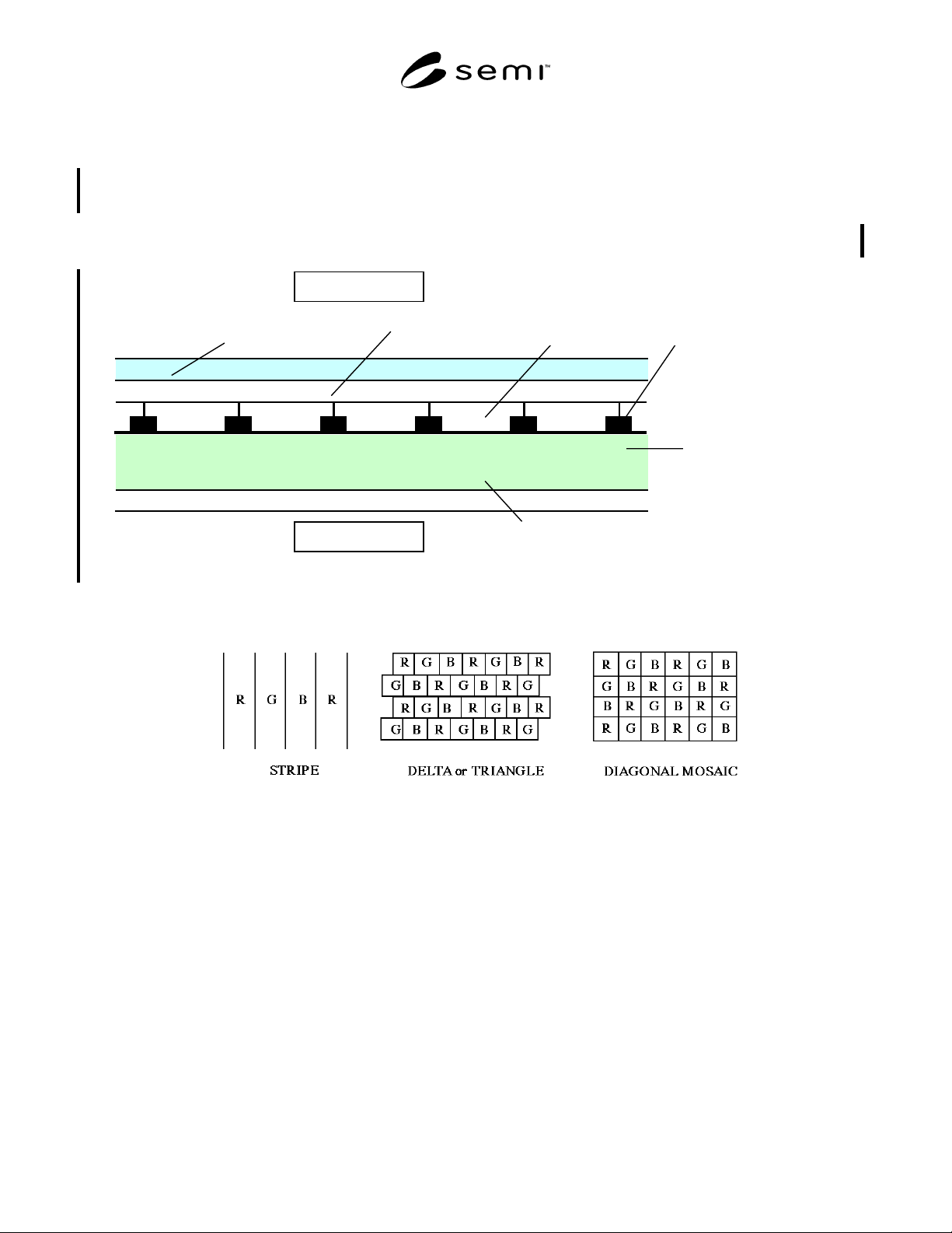
ITO Film
Overcoat Layer
Color Filter Layer
Film Side
Back Side ITO Film
Back Side
Black Matrix
Glass Substrate
Figure 1
Color Filter Elements
Figure 2
Color Filter Array Patterns
NOTICE: SEMI makes no warranties or representations as to the suitability of the standards set forth herein for any
particular application. The determination of the suitability of the standard is solely the responsibility of the user.
Users are cautioned to refer to manufacturer’s instructions, product labels, product data sheets, and other relevant
literature respecting any materials mentioned herein. These standards are subject to change without notice.
The user’s attention is called to the possibility that compliance with this standard may require use of copyrighted
material or of an invention covered by patent rights. By publication of this standard, SEMI takes no position
respecting the validity of any patent rights or copyrights asserted in connection with any item mentioned in this
standard. Users of this standard are expressly advised that determination of any such patent rights or copyrights, and
the risk of infringement of such rights, are entirely their own responsibility.
Copyright by SEMI® (Semiconductor Equipment and Materials
International), 3081 Zanker Road, San Jose, CA 95134. Reproduction o
f
the contents in whole or in part is forbidden without express written
consent of SEMI.

SEMI D15-1296 © SEMI 1996, 2003 1
SEMI D15-1296 (Reapproved 0703)
FPD GLASS SUBSTRATE SURFACE WAVINESS MEASUREMENT
METHOD
This method was technically approved by the Global Flat Panel Display Committee and is the direct
responsibility of the Japanese FPD Materials and Components Committee. Current edition approved by the
Japanese Regional Standards Committee on April 28, 2003. Initially available at www.semi.org June 2003;
to be published July 2003. Originally published December 1996.
1 Purpose
1.1 This document covers the measurement of FPD
glass substrate surface waviness by measuring
instruments employing mechanical stylus, optical
stylus, and optical interferometric measurement
methods.
2 Scope
2.1 This test method is applicable to the documentation
of waviness of all types of glass substrates used for flat
panel displays.
NOTICE: This standard does not purport to address
safety issues, if any, associated with its use. It is the
responsibility of the users of this standard to establish
appropriate safety and health practices and determine
the applicability of regulatory or other limitations prior
to use.
3 Referenced Standards
3.1 SEMI Standards
SEMI D3 — Quality Area Specification for Flat Panel
Display Substrates
SEMI D4 — Method for Referencing Flat Panel
Display Substrates
SEMI D9 — Terminology for FPD Substrates
3.2 ISO Documents
1
ISO 1101 — Technical drawings — Geometrical
Tolerances — Tolerances of Form, Orientation,
Location and Run-Out — Generalities, definitions,
symbols, indications on drawings.
ISO 3274 — Instruments for the Measurement of
Surface Roughness by the Profile Method — Contact
(Stylus) Instruments of Consecutive Profile
Transformation
NOTICE: Unless otherwise indicated, all documents
cited shall be the latest published versions.
1 International Organization for Standardization, ISO Central
Secretariat, 1, rue de Varembé, Case postale 56, CH-1211 Geneva 20,
Switzerland. Telephone: 41.22.749.01.11; Fax: 41.22.733.34.30,
Website: www.iso.ch
4 Terminology
4.1 Definitions
4.1.1 2CR filter — a profile filter equivalent to a series
of two CR filter circuits (see ISO 3274).
4.1.1.1 The standard transmission coefficients at cut-
off wavelength are 75%.
4.1.2 bandpass filtered waviness profile — a profile
obtained by removing the long wavelength form
components and short wavelength roughness
components from a sampled real profile (see Figure 2).
4.1.3 evaluation length, L
e
— the length of the profile
used for assessing the waviness profile under
evaluation. A traced length after deduction of both pre-
travel and post-travel.
4.1.4 FPD waviness, W
fpd
— moving minimum zone
method straightness of waviness. The maximum value
of a minimum zone method straightness of a certain
sampling length within an evaluation length. An
approximation in Appendix 1 can be used as well.
4.1.4.1 Discussion — In fact, it takes a long time to
calculate W
fpd
by the above method because of too large
a number of sampling lengths which are all sampled
data points within evaluation length minus the number
of data points within a sampling length.
4.1.4.2 Therefore, is recommended that the computer
approximation method described in Appendix 1 be used
to save time.
4.1.4.3 Another manual evaluation method is the
following:
1. Prepare the template which has a sampling length
width window.
2. Scan the template with fitting properly on the
recorded chart of bandpass-filtered waviness profile
through the evaluation length.
3. Read out every straightness of the profile within the
window of the template on every fitted position.
4. The maximum value of all of the readings is W
fpd
.

SEMI D15-1296 © SEMI 1996, 2003 2
4.1.5 long wavelength cut-off,
λ
L
— wavelength that
the attenuation ratio of its amplitude becomes a
standard value when the traced profile is passed through
the high-pass wavelength filter which eliminates form
element.
4.1.6 minimum zone method straightness — the
smallest distance between two parallel straight lines
between which all of objective profile is included (see
ISO 1101, Section 3.1).
4.1.7 optical interferometric flatness Measuring
instrument — instrument that analyzes the surface
irregularities of a target, from the distribution of light
intensity of laser interferometer between the target
surface and datum flat.
4.1.8 optical stylus method measuring instrument —
instrument that uses the same profile method that a
stylus method instrument uses. This instrument uses the
displacement transducer to apply the spotlight to the
target surface instead of using the stylus to apply the
spotlight.
4.1.9 phase correct filter — a profile filter which does
not cause phase shifts between total profile and filtered
profile.
4.1.9.1 The standard transmission coefficients at cut-
off wavelength are 50%.
4.1.10 pre-travel (and post-travel), L
p
— eliminated
portions from a traced length for avoiding the profile
distortion caused by transient response of the cut-off
filter.
4.1.10.1 Recommended pre-travel with 2CR filter is
double the long wavelength cut-off, λ
L
, at the beginning
of the traced length and no post-travel.
4.1.10.2 Recommended both pre-travel and post-travel
with phase correct filter are the same as long
wavelength cut-off, λ
L
.
4.1.11 real profile — An intersection of a target surface
with a plane perpendicular to the surface (see Figure 2).
4.1.12 sampling length, L
s
— the length of the profile
for calculations of waviness parameters in an evaluation
length (L
e
).
4.1.13 short wavelength cut-off,
λ
c
— wavelength that
the attenuation ratio of its amplitude becomes a
standard value when the traced profile is passed through
the low-pass wavelength filter which eliminates
roughness element.
4.1.14 streak — a defect whose appearance is a
transparent line on the glass substrate surface. It can
either be caused by a micro surface discontinuity or a
cord due to the heterogeneity of glass composition.
4.1.15 stylus method measuring instrument —
instrument that traces on a section of a surface by a
stylus, records irregularity on the surface in an enlarged
form, and indicates its amplitude as parameters (see
ISO 3274).
4.1.16 traced length — total traversing length of stylus
or spotlight.
4.1.17 waviness — components of surface irregularities
with spatial wavelength intermediate between long
wavelength (flatness) and short wavelength (roughness)
(see Figure 2).
4.1.17.1 Discussion — Especially on FPD substrates,
those components cause visual irregularity of the shade
of the panel due to deviations of the cell gap.
4.1.17.2 Waviness includes not only periodic waviness,
but also streaks.
5 Measuring Instrument
5.1 Method — Stylus method measuring instrument,
optical stylus instrument, or optical interferometric
flatness measuring instrument.
5.2 Stylus or Spotlight
5.2.1 Shape — circular cone or sphere
5.2.2 Tip Radius — from 2µm to 0.8 mm (0.03 inch)
5.2.3 Spotlight Diameter of Optical Stylus Method —
0.2 mm (0.0079 inch) or less
5.2.4 Horizontal Resolution of Interferometer — 0.2
mm (0.0079 inch) or less
5.3 Measuring Force for Stylus Method — 4 mN (0.4
gf) or less
5.4 Sampling Interval — 0.2 mm (0.0079 inch) or less
5.5 Profile Filter — 2CR filter or phase correct filter
5.5.1 Discussion — The filtering method should be
specified because the evaluated value of W
fpd
with
phase correct filter will be smaller than that with 2CR
filter.
6 Measurement Conditions
6.1 Target Surface — The pattern surface (see SEMI
D4, Section 5)
6.2 Long Wavelength Cut-Off,
λ
L
— 8 mm (0.3 inch) or
25 mm (1 inch)
6.3 Short Wavelength Cut-Off,
λ
c
— 0.8 mm (0.03
inch)
6.4 Evaluation Length, L
e
— Is recommended to be Q
ax
or Q
ay
, total edge length of quality area of a substrate. If