semi合集-English.pdf - 第710页
SEMI E92-0302 E © SEMI 1999, 2003 13 • Placement of a finger pinch sensor in the approximately 11 mm space behind SEMI E15.1 D1 is recom mended. A1-8 NOTICE: Adjustment of BOLTS/ Light Unit A1-8.1 In order to maintai n q…
SEMI E92-0302
E
© SEMI 1999, 2003 12
BOLTS/Light
SEMI
E15.1-D1
FOUP
HDP
FDP
BOLTS/Light
Shelf
BOLTS/M
SEMI E15.1-D
SEMI E15.1-
D1
Docking
Stroke
BOLTS/M
BOLTS/M
BOLTS/Light Plane
FDP
BOLTS/M
BDP
BOLTS/Light
BOLTS/M Plane
FOUP
BOLTS/Light
BOLTS/Light
Shelf
BDP
HDP
BOLTS/M Seal
zone
BOLTS/Light
Seal zone
(on the back side)
Top View
Rear View
Side View
Equipment
panel
Forklifts
Exclusion
volume
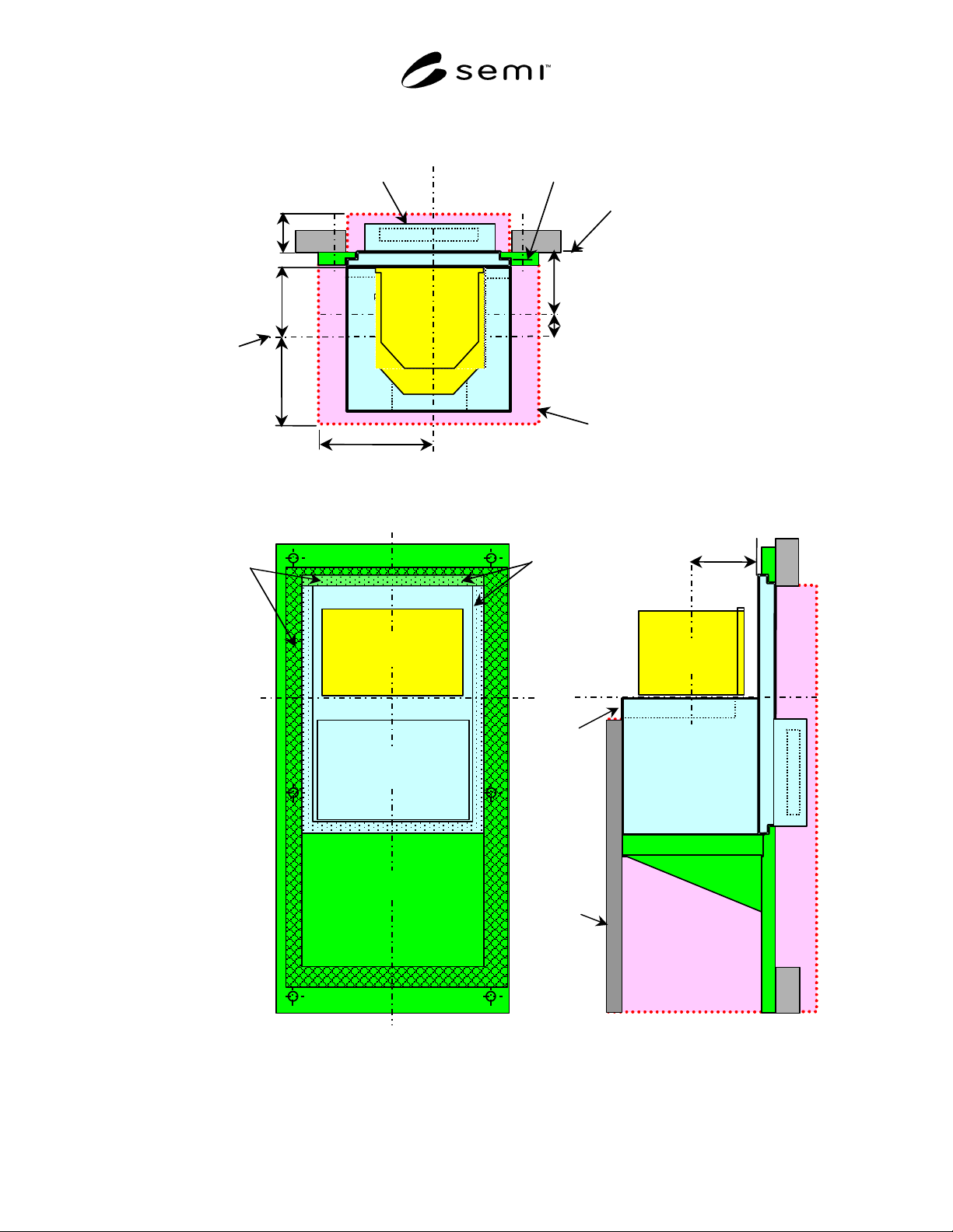
Figure A-1
Usage of BOLTS Shelf (Adopter)

SEMI E92-0302
E
© SEMI 1999, 2003 13
• Placement of a finger pinch sensor in the
approximately 11 mm space behind SEMI E15.1
D1 is recommended.
A1-8 NOTICE: Adjustment of BOLTS/Light Unit
A1-8.1 In order to maintain quick interchangeability
and interoperability and quick attachment/detachment,
adjustment capability should be provided separately by
the box opener/loader and equipment to ensure the port
is positioned correctly with respect to the wafer
handling robot.
A1-8.2 As a result, adjustment means will be necessary
on both the box opener/loader and the equipment. The
box opener/loader may have a capability to calibrate its
critical dimensions in advance, for example, the
parallelism between bottom interface surface and HDP.
In this case, it is not necessary to adjust the box
opener/loader after installation. The equipment should
have a capability to adjust bottom interface plane with
respect to the wafer-handling robot. In case of changing
the box opener/loader in the field, adjustment might
then not be necessary on both the box opener/loader
and the equipment side.
A1-8.3 A fixture may help facilitate this adjustment.
A1-8.4 If fine adjustment is needed after reattaching
the box opener/loader (due to deficient adjustment of
the box opener/loader or equipment side), it may be
done on the equipment side by means of adjusting
screws or other mechanism at bottom interface plane.
A1-9 NOTICE: Control Connection Area
A1-9.1 Connection should be completed after sliding
in the box opener/loader. Disconnection should be
completed before sliding out the box opener/loader.
NOTICE: SEMI makes no warranties or
representations as to the suitability of the standard set
forth herein for any particular application. The
determination of the suitability of the standard is solely
the responsibility of the user. Users are cautioned to
refer to manufacturer’s instructions, product labels,
product data sheets, and other relevant literature
respecting any materials mentioned herein. These
standards are subject to change without notice.
The user’s attention is called to the possibility that
compliance with this standard may require use of copy-
righted material or of an invention covered by patent
rights. By publication of this standard, SEMI takes no
position respecting the validity of any patent rights or
copyrights asserted in connection with any item
mentioned in this standard. Users of this standard are
expressly advised that determination of any such patent
rights or copyrights, and the risk of infringement of
such rights, are entirely their own responsibility.
Copyright by SEMI® (Semiconductor Equipment and Materials
International), 3081 Zanker Road, San Jose, CA 95134. Reproduction o
f
the contents in whole or in part is forbidden without express written
consent of SEMI.

SEMI E99-1104
E
© SEMI 2000, 2004 1
SEMI E99-1104
E
THE CARRIER ID READER/WRITER FUNCTIONAL STANDARD:
SPECIFICATION OF CONCEPTS, BEHAVIOR, AND SERVICES
This specification was technically approved by the Global Information and Control Committee and is the
direct responsibility of the Japanese Information and Control Committee. Current edition approved by the
North American Regional Standards Committee on January 10, 2003. Initially available at www.semi.org
January 2003; to be published March 2003. Originally published February 2000; previously published March
2003.
E
This standard was editorially modified in September 2004 to correct an error. Change was made to Section
R4.1.1.3.
NOTICE: The designation of SEMI E99 was updated during the 1104 publishing cycle to reflect changes to SEMI
E99.1.
1 Purpose
1.1 The purpose of the Carrier ID Reader/Writer
Functional Standard effort is to provide a common
specification for concepts, behavior, and services
(functions) provided by a Carrier ID Reader and a
Carrier ID Reader/Writer to an upstream controller. A
standard interface will increase interchangeability of
Carrier ID Reader/Writers so that users and equipment
suppliers have a wider range of choices.
2 Scope
2.1 The Carrier ID Reader/Writer Interface Standard
addresses the functional requirements for a generic
Carrier ID Reader/Writer interface with an upstream
controller.
2.2 The specification includes required behavior and
required communications for both a Carrier ID Reader
and a Carrier ID Reader/Writer.
2.3 This specification does not require, define, or
prohibit asynchronous messages sent by the Carrier ID
Reader or Reader/Writer.
NOTICE: This standard does not purport to address
safety issues, if any, associated with its use. It is the
responsibility of the users of this standard to establish
appropriate safety and health practices and determine
the applicability of regulatory or other limitations prior
to use.
3 Limitations
3.1 This standard does not define the specific protocol
to be used for the Carrier ID Reader/Writer.
Supplements to this standard are required to describe
how the functions of the Carrier ID Reader/Writer are
implemented for specific protocols.
4 Referenced Standards
4.1 SEMI Standards
SEMI E1.9 Mechanical Specification for Cassettes
Used to Transport and Store 300 mm Wafers
SEMI E15 Specification for Tool Load Port
SEMI E30 Generic Model for Communications and
Control of Manufacturing Equipment (GEM)
SEMI E39 Object Services Standard: Concepts,
Behavior, and Services
SEMI E47.1 Provisional Mechanical Specification
for Boxes and Pods Used to Transport and Store 300
mm Wafers
SEMI E62 Provisional Specification for 300 mm
Front-Opening Interface Mechanical Standard (FIMS)
SEMI E87 — Specification for Carrier Management
(CMS)
NOTICE: As listed or revised, all documents cited
shall be the latest publications of adopted standards.
5 Terminology
5.1 Abbreviations and Acronyms
5.1.1 CIDRW — represents both the Carrier ID Reader
and the Carrier ID Reader/Writer
5.1.2
FOUP — Front Opening Unified Pod
5.2 Definitions
5.2.1 attribute — information about or associated with
some entity or object.
5.2.2 carrier — 1. a container, such as a FOUP or open
cassette, with one or more positions for holding
substrates (SEMI E87). 2. any cassette, box, pod, or
boat that contains wafers.
5.2.3 carrier ID — an identifier for a carrier. A value
that uniquely identifies a given carrier in a factory. The
identifier may be represented physically with any one
of various technologies. For electronic tags with read/