semi合集-English.pdf - 第4053页
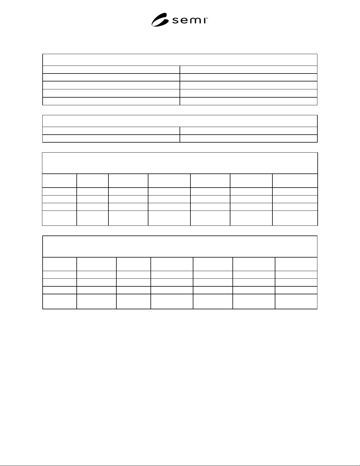
SEMI F53-0600 © SEMI 2000 10 Spike G enerator Equipment Under Test SCOPE AB + - G Figure 4 Transient Susceptibility (Conducted) Te st Setup
SEMI F53-0600 © SEMI 20009
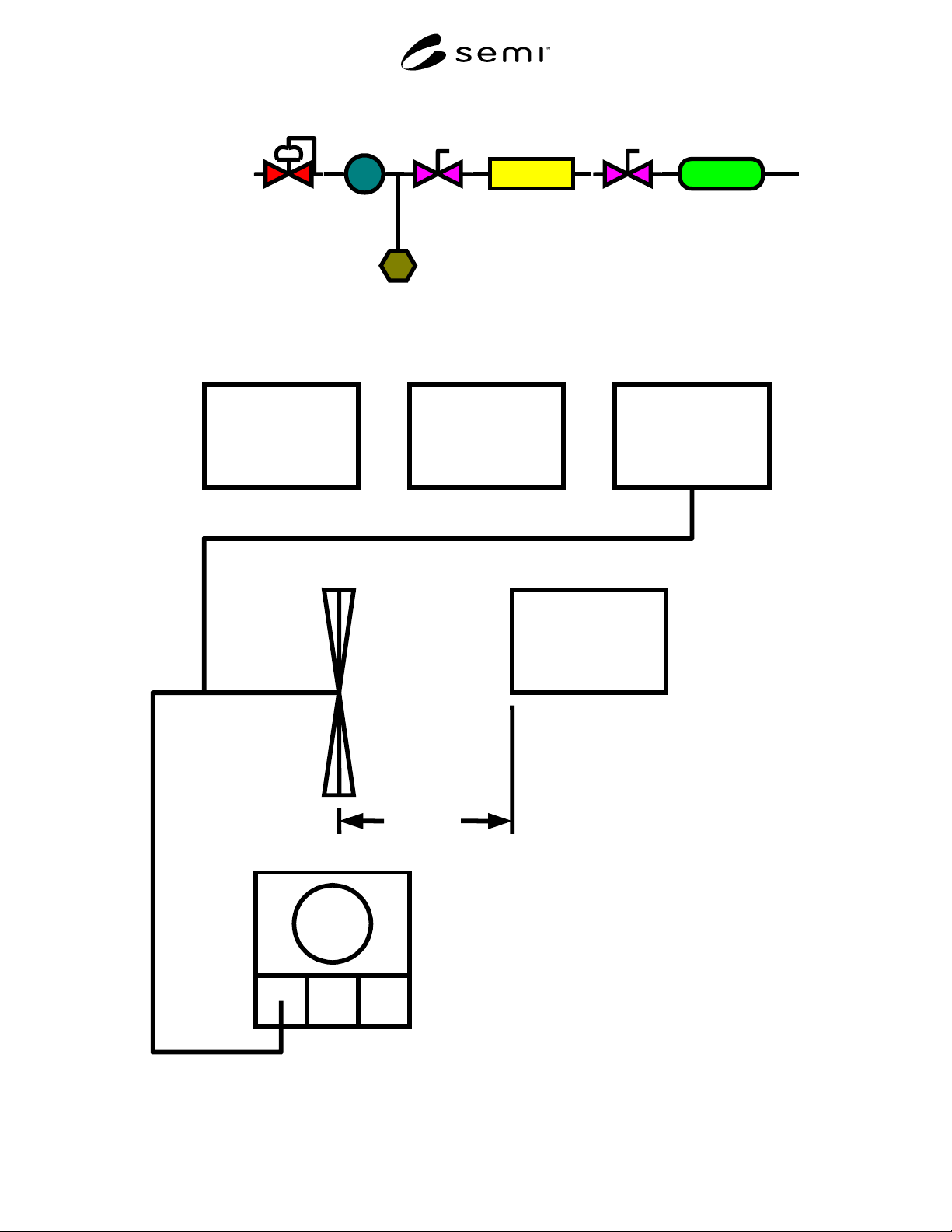
N2 Source
Regulator
Heat
Exchanger
Inlet
Valve
Outlet
Valve
MFC
Flow Standard
Gas
Temperature
Figure 2
MFC Test Setup
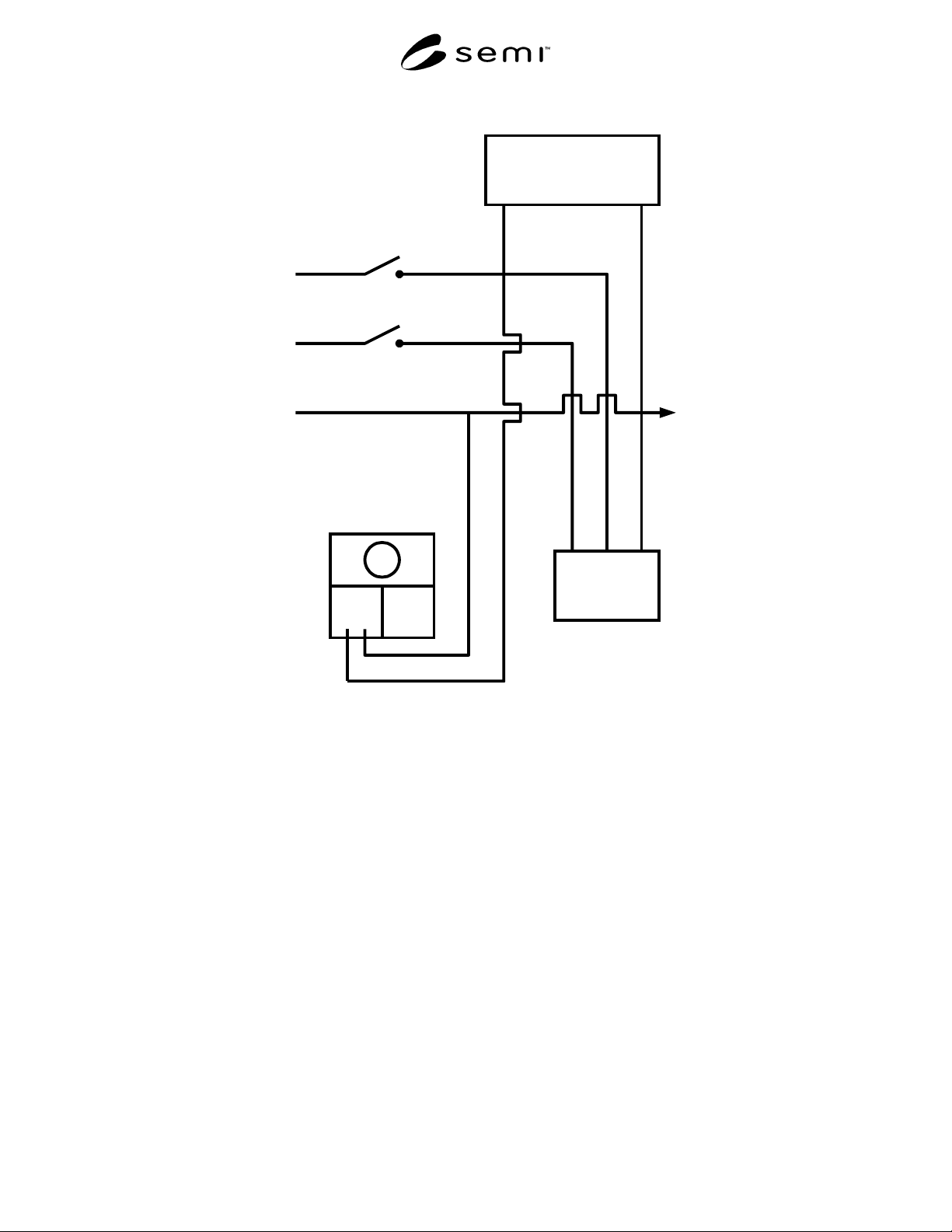
Computer Controller Signal Generator
Power Amplifier
(See NOTE 1.)
Equipment Under Test
A
ntenna (See NOTE 2.)
1M
Oscilloscope
A
NOTE 1: Change Power Amp as Required.
NOTE 2: Change Antenna as Required.
Figure 3
Radiated Electric Field Susceptibility Test Setup
SEMI F53-0600 © SEMI 2000 10
Spike Generator
Equipment Under Test
SCOPE
AB
+
-
G
Figure 4
Transient Susceptibility (Conducted) Test Setup
SEMI F53-0600 © SEMI 200011
Table 1 Data Sheet for EM Susceptibility Testing
Initial Condition
MFC Indicated Output
Flow Standard Output
Ambient Temperature
°C
Gas Temperature
°C
Gas Pressure psig
MFC Cable Shielding and Connector
Cable Shielding
Type of MFC Connector
EM Susceptibility Testing
I. EM Field-Radiated
Data Points Frequency
(Hz)
Field Strength
(V/m)
MFC Indicated
Flow (V)
Flow Standard
Output
MFC Indicated
Flow (%FS)
Flow Standard
(%FS)
1
2
3
:
:
EM Susceptibility Testing
II. EM Field-Conducted
Data Points Spike
Amplitude (V)
Location of
Spike Input
MFC Indicated
Flow (V)
Flow Standard
Output
MFC Indicated
Flow (%FS)
Flow Standard
(%FS)
1
2
3
:
: